Editorial Technical Reference

Control Valves

This page explains how Control Valves is classified within Machinery and Equipment Manufacturing. Technical values and manufacturer relationships are research references; confirm the current specification and supplier evidence for each order.

Technical Definition & Core Assembly

Hydraulic valves that regulate fluid flow, pressure, and direction within hydraulic press systems.
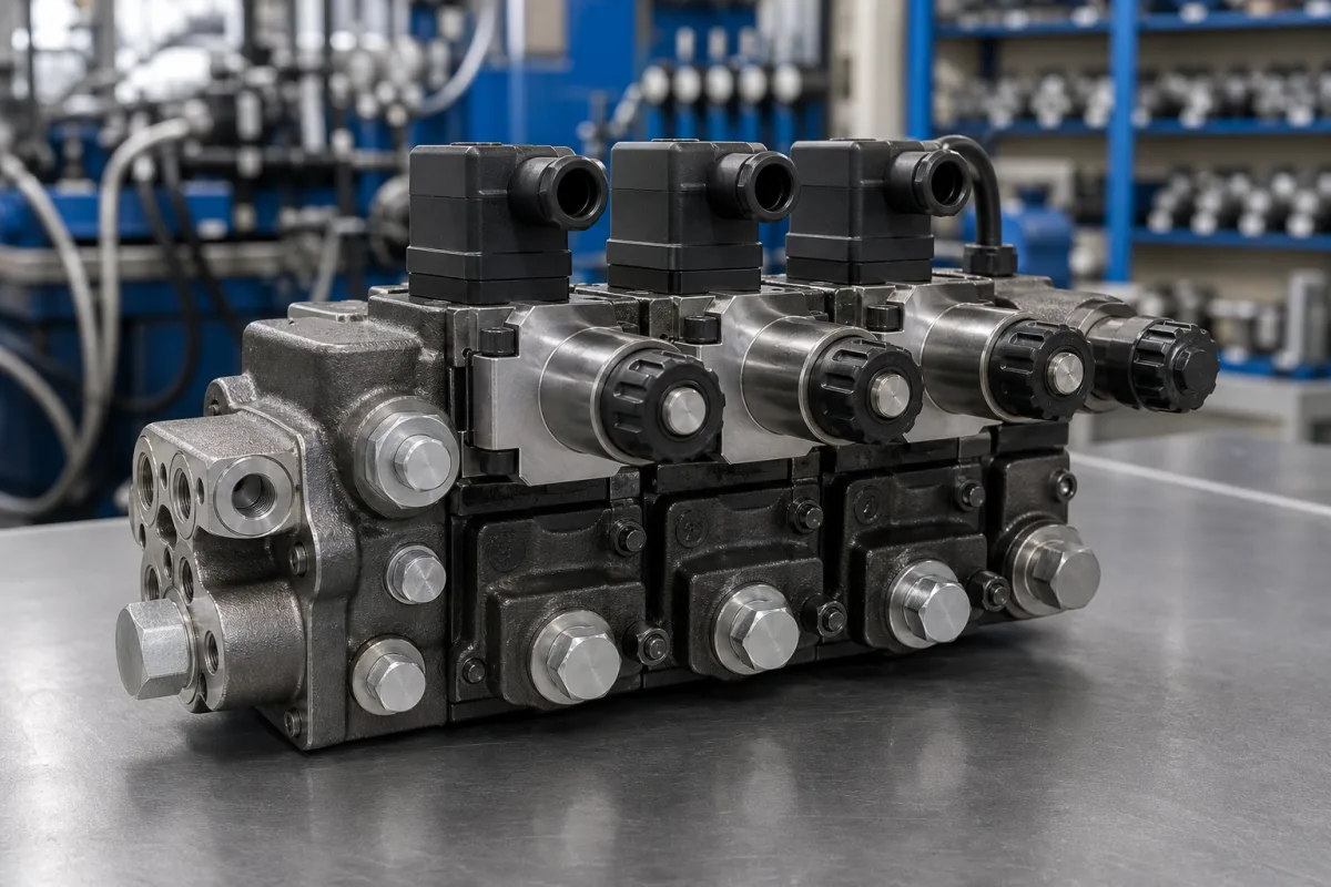
Representative product image. Confirm appearance and specifications with the manufacturer.

Product Specifications

Technical details and manufacturing context for Control Valves

Definition
Control valves are critical components in hydraulic presses that manage the flow of hydraulic fluid to control the speed, force, and direction of the press ram. They ensure precise operation by directing fluid to different actuators and maintaining system pressure within safe operating limits. These valves are typically installed between the pump and the press cylinder, and their configuration determines how the press responds to operator commands or automated control signals. The primary function is to modulate the flow rate, which directly influences the ram speed, and to control pressure, which affects the force exerted by the press. Directional control valves determine the path of fluid flow, enabling the ram to extend, retract, or hold position. Control valves can be manually operated, hydraulically piloted, or electrically actuated, depending on the press design and automation level. They are available in various port sizes, such as 1/4", 1/2", or 3/4", which affect flow capacity and connection compatibility. Common materials include carbon steel, stainless steel, and brass, chosen based on the operating environment and fluid compatibility. Proper selection requires consideration of the press's required flow rate, pressure rating, and control method. Installation and maintenance must follow the manufacturer's specifications, and regular inspection is necessary to detect wear, leakage, or sticking. Verification of model-specific parameters, such as port size and pressure ratings, should be confirmed with the legal manufacturer or supplier before procurement or replacement. Control valves are not safety devices by themselves; they must be integrated with appropriate safety circuits and pressure relief mechanisms. Failure to maintain or correctly adjust these valves can lead to erratic press movement, reduced efficiency, or unsafe operating conditions. Therefore, understanding the valve's operating principle and maintenance requirements is essential for reliable and safe hydraulic press operation.
Working Principle
Control valves operate by using mechanical, hydraulic, or electrical signals to adjust the position of internal spools or poppets, which open or close fluid passages. This regulates the flow rate, pressure, or direction of hydraulic fluid to the press cylinders, enabling controlled movement and force application. The spool or poppet movement changes the cross-sectional area of the flow path, thereby controlling the amount of fluid passing through. In pressure control valves, a spring or pilot pressure balances against the system pressure to maintain a set level. Directional control valves shift the spool to connect different ports, directing fluid to the appropriate cylinder chamber. The actuation method can be manual, solenoid-operated, or hydraulically piloted, depending on the control system.
Common Materials
Carbon Steel, Stainless Steel, Brass
Technical Parameters

What to specify in your RFQ

  • Port size (e.g., 1/4", 1/2", 3/4") determines flow capacity and connection compatibility in mm

These are the quantities to specify to the manufacturer when sizing or requesting a quote. The manufacturer's own documentation governs the exact figures and applicable standard.

Components / BOM
  • Valve Body
    Main housing that contains internal components and provides fluid passages
  • Spool/Poppet Part
    Moving element that opens/closes fluid passages to control flow direction
  • Spring Part
    Provides return force to reset valve position
  • Seals Part
    Prevent fluid leakage between moving parts and housing
  • Solenoid Coil
    Electromagnetic actuator for electrically operated valves

Applied To / Applications

This component is essential for the following industrial systems and equipment:

Industrial Ecosystem & Supply Chain Structure

Complementary Systems
Downstream Applications
Specialized Tooling

Application Fit & Sizing Matrix

Operational Limits
pressure: Up to 350 bar
flow rate: 0.5 to 500 L/min
temperature: -20°C to 120°C
slurry concentration: Up to 10% solids by weight
Media Compatibility
✓ Hydraulic oil (ISO VG 32-68) ✓ Water-glycol fluids ✓ Phosphate ester fluids
Unsuitable: Highly corrosive chemicals (e.g., strong acids, chlorinated solvents)
Sizing Data Required
  • Required flow rate (L/min)
  • System pressure (bar)
  • Fluid viscosity (cSt)

Reliability & Engineering Risk Analysis

Failure Mode & Root Cause
Sticking or binding
Cause: Accumulation of process media deposits, corrosion products, or foreign particles in the valve body or on the trim components, often exacerbated by high temperatures or incompatible materials.
Internal leakage (failure to shut off)
Cause: Wear or damage to the valve seat and disc/plug due to erosion, cavitation, or mechanical over-torquing during operation, compromising the sealing surfaces.
Maintenance Indicators
  • Excessive hissing or whistling noise from the valve during operation, indicating internal leakage or flow restriction.
  • Visible external leakage of process fluid from the valve body, stem packing, or connections, or signs of corrosion and weeping.
Engineering Tips
  • Implement routine condition monitoring such as valve signature testing and acoustic emission testing to detect early signs of wear, sticking, or leakage before catastrophic failure.
  • Ensure proper sizing and selection of control valves for the specific service conditions (pressure, temperature, flow characteristics) to avoid cavitation, flashing, or excessive velocities that accelerate erosion.

Indicative industry ranges for design and RFQ preparation. Confirm the exact figures and applicable standard with the manufacturer before specifying.

Compliance & Manufacturing Standards

Applicable Standards
ISO 15848-1:2015 (Leakage classification and testing of valve stem seals) ANSI/ISA 75.01.01 (Flow equations for sizing control valves) DIN EN 12516-1 (Pressure design of valve bodies)

Quoted from the published standard.

Manufacturing Precision
  • Bore diameter: +/-0.05mm
  • Surface flatness of flange faces: 0.1mm
Quality Inspection
  • Hydrostatic shell test (per API 598)
  • Valve seat leakage test (per ANSI/FCI 70-2)

Manufacturers of Control Valves

Manufacturer profiles associated with Control Valves.

Sourcing Control Valves from China?
Tell us your specification and target quantity — we will match it against manufacturer records and come back with the factories that fit.
Request manufacturers We manufacture this

Manufacturer listings support early research and capability understanding. They are not certification, ranking, or transaction guarantees.

Technical documentation
Request current drawings, revision history, and a signed specification sheet.
Manufacturing capability
Verify equipment lists, process limits, capacity, and representative production evidence.
Inspection readiness
Confirm test methods, calibrated equipment, sampling plans, and traceable reports.
Supplier transparency
Check the legal entity, factory address, ownership, certifications, and direct contacts.

CNFX does not score or rank suppliers. Buyers must verify all claims and documents with the legal manufacturer before ordering.

Supply Chain Compatible Machinery & Devices

Automated Powder Coating System

Integrated industrial system for applying dry powder coatings to metal substrates.

Explore Specs →
Centrifugal Pump Impeller

The centrifugal pump impeller is a critical rotating component that converts mechanical energy from the motor into kinetic energy in fluid systems.

Explore Specs →
High-Precision CNC Laser Cutting Machine

Computer-controlled industrial machine using focused laser beams to cut sheet metal with micron-level accuracy.

Explore Specs →
Industrial-Grade Hydraulic Cylinder Piston Rod

This industrial-grade piston rod is a precision-ground cylindrical component designed for use in hydraulic cylinders.

Explore Specs →

Frequently Asked Questions

What are the main types of control valves used in hydraulic presses?

The main types are flow control valves, pressure control valves, and directional control valves. Flow control valves regulate the speed of the ram by adjusting the flow rate. Pressure control valves maintain system pressure within safe limits. Directional control valves determine the path of fluid flow to control the direction of movement.

How do I select the right control valve for my hydraulic press?

Selection depends on the required flow rate, pressure rating, port size, and control method. You must consider the press's specifications and operating conditions. Always verify the valve's parameters, such as port size (e.g., 1/4", 1/2", 3/4") and pressure rating, with the legal manufacturer or supplier to ensure compatibility.

What materials are commonly used for control valves?

Common materials include carbon steel, stainless steel, and brass. The choice depends on the hydraulic fluid, operating environment, and required corrosion resistance. Confirm the material suitability with the manufacturer for your specific application.

What maintenance is required for control valves?

Regular inspection for leakage, wear, and sticking is necessary. Follow the manufacturer's maintenance schedule, including cleaning and replacing seals or worn parts. Always verify that the valve is functioning correctly before operation to ensure safety and performance.

Data Basis

Editorial classification, named public sources where available, and source-reviewed manufacturer records.

Preliminary Technical Classification
This page supports structured research, RFQ preparation, and supplier evaluation. It does not replace buyer-led supplier qualification, standards review, or technical approval.
Buyer enquiry

Request manufacturing insight for Control Valves

Ask for use case, specification boundaries, supplier type, and RFQ preparation information for this product.

Where it goes
Straight to the CNFX editorial desk, and to the manufacturer if this product is linked to a claimed profile. Nothing is broadcast to a supplier list.
Your details stay here
We do not sell or rent enquiry data, and we do not add you to a mailing list. Used only to answer this request.
No commission, no middleman
CNFX is a directory. We take no cut of any order and never negotiate on a supplier's behalf.
What we don't claim
A listing is not an endorsement. Qualify every supplier and verify every figure yourself before ordering.

Your business information is used only to process this request.

Thank you! Your message has been sent. We'll respond within 1–3 business days.
Sorry, we couldn't send your message. Please try again, or email us at contact@cnfx.com.

Need to Manufacture Control Valves?

Compare manufacturer profiles with relevant product and process capability.

Previous Product
Z-axis Ram/Spindle
Last Product
Get QuotesChat