Editorial Technical Reference

Infrared Emitter Array

This page explains how Infrared Emitter Array is classified within Machinery and Equipment Manufacturing. Technical values and manufacturer relationships are research references; confirm the current specification and supplier evidence for each order.

Technical Definition & Core Assembly

A modular assembly of multiple infrared emitters arranged in a pattern to provide uniform heating within an IR drying/curing tunnel.
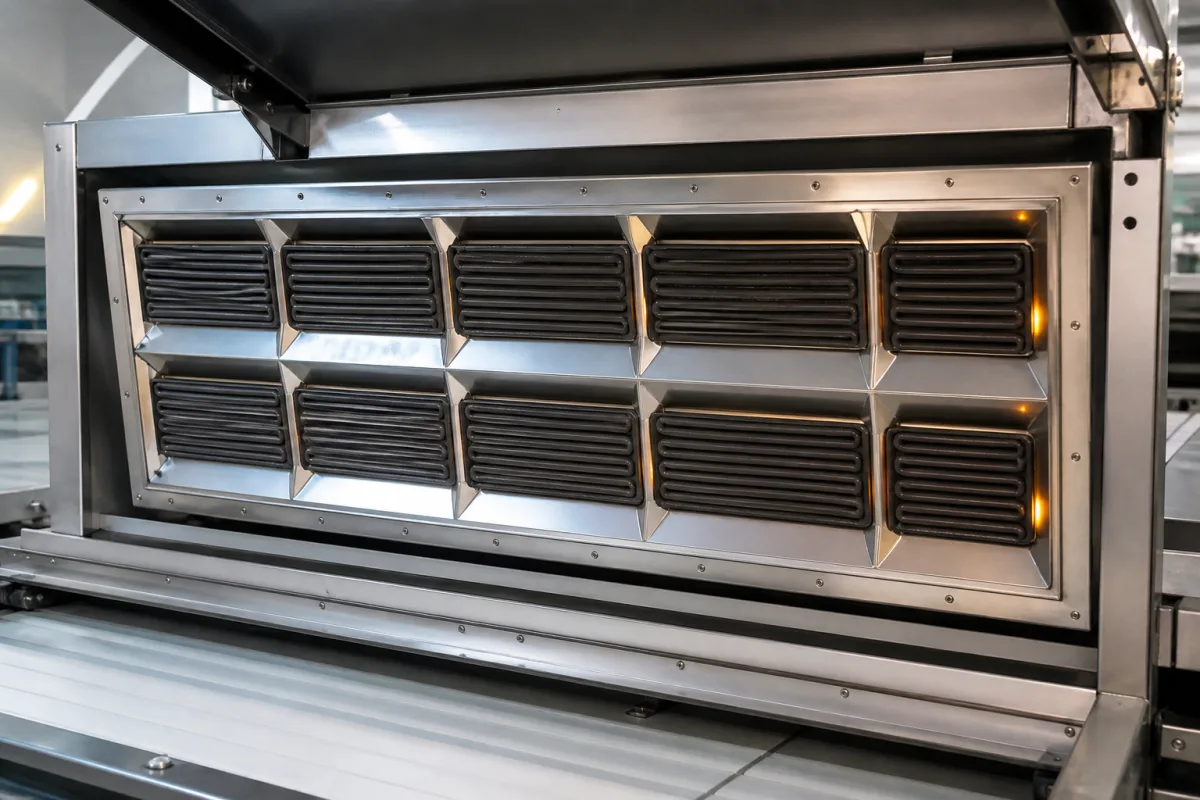
Representative product image. Confirm appearance and specifications with the manufacturer.

Product Specifications

Technical details and manufacturing context for Infrared Emitter Array

Definition
The infrared emitter array is a critical component of IR drying/curing tunnels, consisting of multiple individual infrared heating elements (emitters) arranged in a specific geometric configuration (e.g., linear, grid, or panel). Its primary function is to generate and project controlled infrared radiation onto the surface of materials passing through the tunnel, facilitating rapid and efficient drying, curing, or heating processes by transferring thermal energy directly to the target. The array is designed for integration into industrial machinery, typically as a modular section that can be sized to fit the tunnel's width and length. It operates on AC input voltages ranging from 220 to 480 V, with total power consumption between 10 and 50 kW depending on the array length. Radiant power density ranges from 30 to 80 kW/m², and emission wavelengths fall within 2.0 to 4.0 μm, suitable for efficient IR drying. The array achieves temperature uniformity of ±5% across its width, with emitter surface temperatures reaching 400–800 °C. It is built with materials such as quartz glass, tungsten filaments (for halogen types), ceramic elements, nickel-chromium alloy heating wire, and aluminum reflectors/housings. The ingress protection rating is IP54 to IP65 per IEC 60529, indicating dust and water resistance. Standard array widths range from 500 to 2000 mm, and lengths from 1000 to 6000 mm, with modular sections for customization. Weight varies from 50 to 300 kg depending on size and materials. The typical lifespan is 5000 to 10000 operational hours. Operating temperature range is -20 to 60 °C. These values are reference ranges; actual specifications must be confirmed with the legal manufacturer or supplier for the specific model and application. The array is a component, not a standalone system, and requires proper electrical and mechanical integration. Verification of parameters and compliance with applicable standards is essential before procurement.
Working Principle
The array operates by electrically powering its individual infrared emitters (typically quartz tubes, ceramic elements, or halogen lamps), which convert electrical energy into infrared radiation. This radiation is emitted in specific wavelengths (short-wave, medium-wave, or long-wave IR) and directed onto the target material. The material absorbs this radiation, causing molecular vibration and generating heat from within, leading to efficient surface or through-heating for drying, curing, or pre-heating applications. The arrangement of emitters in a pattern ensures uniform heat distribution across the material's surface. The array's design allows for controlled power input and wavelength selection to match the absorption characteristics of the material being processed. Proper operation requires correct electrical supply, thermal management, and alignment within the tunnel. Maintenance signals include uneven heating, reduced output, or emitter failure. The array's performance is influenced by factors such as emitter condition, reflector cleanliness, and ambient temperature. It is not designed for outdoor use without additional protection. The working principle is based on radiative heat transfer, which is distinct from convective or conductive methods.
Common Materials
Quartz Glass, Tungsten Filament (for halogen types), Ceramic (for ceramic emitter types), Nickel-Chromium Alloy (heating wire), Aluminum (reflector/housing)
Technical Parameters
ParameterTypical rangeNotes & selection driver
Emission Wavelength2.0–4.0 μmPeak wavelength range for efficient IR drying
Radiant Power Density30–80 kW/m²Higher density increases drying speed
Input Voltage220–480 V ACThree-phase or single-phase options
Power Consumption10–50 kWTotal power for array length
Operating Temperature-20–60 °CAmbient temperature range
Max Surface Temperature400–800 °CEmitter surface temperature
Temperature Uniformity±5 %Across the array width
Ingress ProtectionIP54–IP65Dust and water resistanceIEC 60529
Array Width500–2000 mmStandard widths; custom available
Array Length1000–6000 mmModular sections for length
Weight50–300 kgDepends on size and materials
Emitter MaterialQuartzHigh thermal shock resistance
Lifespan5000–10000 hAverage operational hours

Ranges are indicative industry figures for RFQ preparation, not a supplier commitment. Confirm every value and standard with the legal manufacturer before ordering.

Components / BOM
  • Infrared Emitter Tube/Lamp Part
    The core heating element that generates infrared radiation when powered.
    Material: Quartz glass, tungsten, ceramic
  • Reflector Part
    Directs and focuses the emitted infrared radiation towards the target material, improving efficiency.
    Material: Polished aluminum, gold-coated surface
  • Electrical Connector/ Terminal Block Part
    Provides secure electrical connections for powering the emitters.
    Material: Ceramic, high-temperature plastic, brass
  • Mounting Frame/Housing
    Holds all emitters and components in the specified array configuration and provides structural support and protection.
    Material: Stainless steel, aluminum alloy
  • Insulation/Spacer Part
    Provides electrical isolation and thermal management between emitters and the housing.
    Material: Mica, ceramic fiber

Applied To / Applications

This component is essential for the following industrial systems and equipment:

Industrial Ecosystem & Supply Chain Structure

Complementary Systems
Downstream Applications
Specialized Tooling

Application Fit & Sizing Matrix

Operational Limits
pressure: Atmospheric to 1.5 bar (sealed enclosure dependent)
other spec: Wavelength: 2-5 μm (typical for drying/curing), Power density: 5-50 kW/m² configurable, Response time: <1 sec
temperature: Ambient to 400°C (operating), up to 600°C (peak)
Media Compatibility
✓ Water-based coatings/inks ✓ Polymer film curing (e.g., PET, PP) ✓ Food product surface drying
Unsuitable: Explosive or flammable vapor environments (due to ignition risk from high surface temperatures)
Sizing Data Required
  • Required thermal energy input (kW/m²) based on material properties and process speed
  • Tunnel dimensions and emitter-to-target distance
  • Desired temperature profile and dwell time in the curing zone

Reliability & Engineering Risk Analysis

Failure Mode & Root Cause
Thermal degradation of emitter elements
Cause: Overheating due to inadequate heat dissipation, excessive current, or prolonged operation beyond design limits, leading to reduced output intensity and eventual failure.
Optical surface contamination or damage
Cause: Accumulation of dust, moisture, or chemical residues on emitter surfaces or lenses, causing scattering, absorption, or physical degradation of infrared output.
Maintenance Indicators
  • Visible discoloration, dark spots, or clouding on emitter surfaces or protective windows
  • Audible buzzing, crackling, or irregular operation sounds indicating electrical arcing or component stress
Engineering Tips
  • Implement regular cleaning protocols using appropriate solvents and lint-free materials to maintain optical clarity and prevent contamination buildup.
  • Ensure proper thermal management through adequate ventilation, heat sinks, or active cooling systems, and monitor operating temperatures to prevent thermal stress.

Indicative industry ranges for design and RFQ preparation. Confirm the exact figures and applicable standard with the manufacturer before specifying.

Compliance & Manufacturing Standards

Applicable Standards
ISO 12354:2018 - Optical radiation safety of laser products ANSI Z136.1 - Safe Use of Lasers IEC 60825-1:2014 - Safety of laser products

Quoted from the published standard.

Manufacturing Precision
  • Wavelength accuracy: +/- 5 nm
  • Output power consistency: +/- 3% across array
Quality Inspection
  • Radiometric power output verification
  • Spectral distribution analysis

Manufacturers of Infrared Emitter Array

Manufacturer profiles associated with Infrared Emitter Array.

Sourcing Infrared Emitter Array from China?
Tell us your specification and target quantity — we will match it against manufacturer records and come back with the factories that fit.
Request manufacturers We manufacture this

Manufacturer listings support early research and capability understanding. They are not certification, ranking, or transaction guarantees.

Technical documentation
Request current drawings, revision history, and a signed specification sheet.
Manufacturing capability
Verify equipment lists, process limits, capacity, and representative production evidence.
Inspection readiness
Confirm test methods, calibrated equipment, sampling plans, and traceable reports.
Supplier transparency
Check the legal entity, factory address, ownership, certifications, and direct contacts.

CNFX does not score or rank suppliers. Buyers must verify all claims and documents with the legal manufacturer before ordering.

Supply Chain Compatible Machinery & Devices

Heavy-Duty CNC Plasma Cutting Machine

The Heavy-Duty CNC Plasma Cutting Machine is a standalone industrial device designed for cutting conductive metals such as steel, stainless steel, aluminum, and copper alloys.

Explore Specs →
Automated Powder Coating System

Integrated industrial system for applying dry powder coatings to metal substrates.

Explore Specs →
Centrifugal Pump Impeller

The centrifugal pump impeller is a critical rotating component that converts mechanical energy from the motor into kinetic energy in fluid systems.

Explore Specs →
High-Precision CNC Laser Cutting Machine

Computer-controlled industrial machine using focused laser beams to cut sheet metal with micron-level accuracy.

Explore Specs →

Frequently Asked Questions

What are the typical emission wavelengths for this infrared emitter array?

The array emits infrared radiation in the wavelength range of 2.0 to 4.0 μm, which is suitable for efficient IR drying. This range corresponds to medium-wave infrared, but the actual wavelength depends on the emitter type (quartz, ceramic, or halogen) and operating temperature. Verify the specific wavelength for your application with the manufacturer.

How is the array powered and what is the power consumption?

The array operates on AC input voltages from 220 to 480 V, with options for single-phase or three-phase. Total power consumption ranges from 10 to 50 kW depending on the array length and emitter configuration. The radiant power density is 30 to 80 kW/m². Ensure your facility's electrical supply matches the requirements.

What is the ingress protection rating and why is it important?

The array has an ingress protection rating of IP54 to IP65 per IEC 60529, indicating resistance to dust and water. This is important for industrial environments where moisture or particulates may be present. The rating ensures safe operation and longevity, but the actual level should be confirmed for the specific model.

Can the array be customized to fit different tunnel sizes?

Yes, the array is modular and available in standard widths from 500 to 2000 mm and lengths from 1000 to 6000 mm. Custom sizes may be available from the manufacturer. The array can be configured in linear, grid, or panel patterns to suit the tunnel's design. Always confirm dimensions and configuration with the supplier.

Data Basis

Editorial classification, named public sources where available, and source-reviewed manufacturer records.

Preliminary Technical Classification
This page supports structured research, RFQ preparation, and supplier evaluation. It does not replace buyer-led supplier qualification, standards review, or technical approval.
Buyer enquiry

Request manufacturing insight for Infrared Emitter Array

Ask for use case, specification boundaries, supplier type, and RFQ preparation information for this product.

Where it goes
Straight to the CNFX editorial desk, and to the manufacturer if this product is linked to a claimed profile. Nothing is broadcast to a supplier list.
Your details stay here
We do not sell or rent enquiry data, and we do not add you to a mailing list. Used only to answer this request.
No commission, no middleman
CNFX is a directory. We take no cut of any order and never negotiate on a supplier's behalf.
What we don't claim
A listing is not an endorsement. Qualify every supplier and verify every figure yourself before ordering.

Your business information is used only to process this request.

Thank you! Your message has been sent. We'll respond within 1–3 business days.
Sorry, we couldn't send your message. Please try again, or email us at contact@cnfx.com.

Need to Manufacture Infrared Emitter Array?

Compare manufacturer profiles with relevant product and process capability.

Previous Product
Infeed/Outfeed Conveyor
Next Product
Insertion Actuator
Get QuotesChat