Editorial Technical Reference

Length Measuring System

This page explains how Length Measuring System is classified within Machinery and Equipment Manufacturing. Technical values and manufacturer relationships are research references; confirm the current specification and supplier evidence for each order.

Technical Definition & Core Assembly

A precision measurement subsystem integrated within a cutting system to accurately determine and control material length during processing.
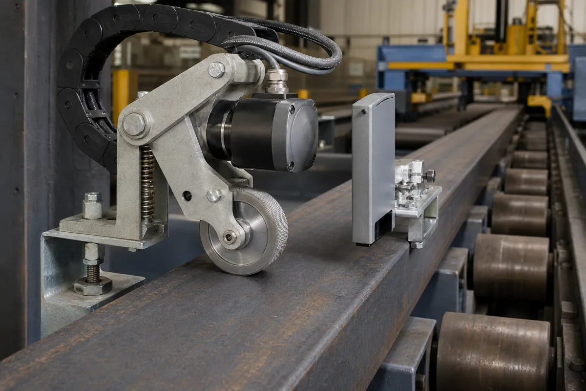
Length Measuring System in a manufacturing environment
Representative product image. Confirm appearance and specifications with the manufacturer.

Product Specifications

Technical details and manufacturing context for Length Measuring System

Definition
The Length Measuring System is a critical component of industrial cutting systems that provides real-time, high-precision measurement of material length to ensure accurate cutting operations. It typically consists of sensors, encoders, and control units that work together to monitor material feed, calculate required cut lengths, and provide feedback to the cutting mechanism for precise positioning and operation. The system is designed for integration into various cutting machinery, such as shears, saws, or guillotines, where precise length control is essential. It supports measuring ranges from 0.5 to 100 meters, with an option to extend up to 200 meters on request. Measurement accuracy is ±0.05 mm under standard conditions, as per ISO 5725-1, and resolution is 0.01 mm, with higher resolution available. The system can measure at speeds up to 120 m/min without loss of accuracy. It operates within a temperature range of -10°C to 50°C, with potential accuracy degradation below -10°C, and can be stored at -20°C to 70°C. Relative humidity should be maintained between 10% and 90% non-condensing. The system requires a 24 V DC supply voltage (±10%) with reverse polarity protection, and consumes up to 15 W typically. Ingress protection ratings range from IP54 to IP65, suitable for dusty environments. Output interfaces include RS485 and Ethernet, with Modbus RTU/TCP optional. The weight varies from 2.5 to 5.0 kg depending on the measuring range. Materials used include aluminum alloy, stainless steel, optical glass, and electronic components. The system is designed for industrial environments and must be verified for specific model applications. Always confirm model-specific values and standards with the legal manufacturer or supplier.
Working Principle
The system operates by using optical, laser, or contact-based sensors to detect material movement and position. Encoders measure displacement as material passes through the system, while processing units calculate exact lengths based on feed rates and sensor inputs. This data is then transmitted to the cutting control system to trigger cuts at predetermined intervals with millimeter-level accuracy.
Common Materials
Aluminum alloy, Stainless steel, Optical glass, Electronic components
Technical Parameters
ParameterTypical rangeNotes & selection driver
Measuring Range0.5–100 mCustomizable up to 200 m on request
Measurement Accuracy±0.05 mmUnder standard conditionsISO 5725-1
Resolution0.01 mmHigher resolution available
Measuring Speed0–120 m/minMaximum speed without accuracy loss
Operating Temperature-10–50 °CBelow -10°C accuracy may degradeIEC 60068-2-1
Storage Temperature-20–70 °CNon-condensing
Relative Humidity10–90 %Non-condensingIEC 60068-2-78
Supply Voltage24 ±10% V DCReverse polarity protectedIEC 61131-2
Power Consumption≤15 WTypical at 24 V DC
Ingress ProtectionIP54–IP65IP65 for dusty environmentsIEC 60529
Output InterfaceRS485, EthernetModbus RTU/TCP optionalIEC 61158
Weight2.5–5.0 kgDepends on measuring range

Ranges are indicative industry figures for RFQ preparation, not a supplier commitment. Confirm every value and standard with the legal manufacturer before ordering.

Components / BOM
  • Measurement Sensor
    Detects material presence and position for length calculation
    Material: Stainless steel housing with optical components
  • Encoder Wheel Part
    Measures material displacement by counting rotations as material passes
    Material: Rubber or polyurethane with aluminum core
  • Signal Processor
    Converts sensor inputs into digital length measurements
    Material: Electronic circuit board with microprocessors
  • Mounting Bracket Part
    Secures the measurement system to the cutting machine frame
    Material: Steel or aluminum alloy

Applied To / Applications

This component is essential for the following industrial systems and equipment:

Industrial Ecosystem & Supply Chain Structure

Complementary Systems
Downstream Applications
Specialized Tooling

Application Fit & Sizing Matrix

Operational Limits
accuracy: ±0.1 mm or ±0.05% of measured length (whichever is greater)
pressure: Atmospheric pressure only (non-pressurized system)
temperature: 0°C to 50°C (operating), -10°C to 60°C (storage)
repeatability: ±0.05 mm
response time: <100 ms
measurement range: 10 mm to 6000 mm
Media Compatibility
✓ Metals (steel, aluminum, copper) ✓ Plastics (PVC, polycarbonate, acrylic) ✓ Composite materials (fiberglass, carbon fiber)
Unsuitable: High-vibration environments with amplitude >0.5 mm at frequencies >50 Hz
Sizing Data Required
  • Maximum material length to be measured
  • Required measurement accuracy (±mm or %)
  • Material surface characteristics (reflectivity, color, texture)

Reliability & Engineering Risk Analysis

Failure Mode & Root Cause
Optical Component Degradation
Cause: Accumulation of dust, oil mist, or particulates on lenses, sensors, or laser windows, leading to signal attenuation, beam scattering, or calibration drift.
Encoder or Scale Contamination/Fouling
Cause: Ingress of coolant, metal chips, or debris into the linear/rotary encoder or scale system, causing signal dropout, interpolation errors, or physical damage to grating/read head.
Maintenance Indicators
  • Intermittent or erratic measurement readings, or complete loss of signal during operation.
  • Unusual audible noise (grinding, clicking) from the measuring head or drive mechanism during traversal.
Engineering Tips
  • Implement a regular cleaning and inspection schedule for optical paths and scales using approved, lint-free wipes and compatible cleaning solvents, ensuring the system is powered down during cleaning.
  • Ensure proper sealing and positive air purge (if equipped) to maintain a clean internal environment, and verify alignment and mounting stability to prevent vibration-induced errors or mechanical wear.

Indicative industry ranges for design and RFQ preparation. Confirm the exact figures and applicable standard with the manufacturer before specifying.

Compliance & Manufacturing Standards

Applicable Standards
ISO 10360-2:2009 - Acceptance and reverification tests for coordinate measuring machines (CMMs) ANSI/ASME B89.1.13 - Dimensional Measuring Equipment - Micrometers DIN 862 - Vernier calipers; requirements, testing

Quoted from the published standard.

Manufacturing Precision
  • Linear measurement accuracy: +/-0.005 mm
  • Repeatability: +/-0.002 mm
Quality Inspection
  • Calibration verification against traceable standards (e.g., gauge blocks)
  • Environmental compensation testing (temperature, humidity)

Manufacturers of Length Measuring System

Manufacturer profiles associated with Length Measuring System.

Sourcing Length Measuring System from China?
Tell us your specification and target quantity — we will match it against manufacturer records and come back with the factories that fit.
Request manufacturers We manufacture this

Manufacturer listings support early research and capability understanding. They are not certification, ranking, or transaction guarantees.

Share this page
Technical documentation
Request current drawings, revision history, and a signed specification sheet.
Manufacturing capability
Verify equipment lists, process limits, capacity, and representative production evidence.
Inspection readiness
Confirm test methods, calibrated equipment, sampling plans, and traceable reports.
Supplier transparency
Check the legal entity, factory address, ownership, certifications, and direct contacts.

CNFX does not score or rank suppliers. Buyers must verify all claims and documents with the legal manufacturer before ordering.

Supply Chain Compatible Machinery & Devices

Heavy-Duty CNC Plasma Cutting Machine

The Heavy-Duty CNC Plasma Cutting Machine is a standalone industrial device designed for cutting conductive metals such as steel, stainless steel, aluminum, and copper alloys.

Explore Specs →
Automated Powder Coating System

Integrated industrial system for applying dry powder coatings to metal substrates.

Explore Specs →
Centrifugal Pump Impeller

The centrifugal pump impeller is a critical rotating component that converts mechanical energy from the motor into kinetic energy in fluid systems.

Explore Specs →
High-Precision CNC Laser Cutting Machine

Computer-controlled industrial machine using focused laser beams to cut sheet metal with micron-level accuracy.

Explore Specs →

Frequently Asked Questions

What is the measuring range of this system?

The standard measuring range is 0.5 to 100 meters, with an option to extend up to 200 meters on request. Always confirm the exact range for your specific model with the manufacturer.

What accuracy can be expected?

Under standard conditions, the measurement accuracy is ±0.05 mm, as per ISO 5725-1. However, actual performance may vary depending on installation and environmental factors, so verify with the supplier.

What output interfaces are available?

The system provides RS485 and Ethernet interfaces, with Modbus RTU/TCP as an option. These allow integration with various control systems. Confirm compatibility with your equipment.

What are the environmental operating limits?

The system operates in temperatures from -10°C to 50°C, with accuracy potentially degrading below -10°C. Storage temperature is -20°C to 70°C, and relative humidity should be 10-90% non-condensing. Ensure these conditions are met.

Data Basis

Editorial classification, named public sources where available, and source-reviewed manufacturer records.

Preliminary Technical Classification
This page supports structured research, RFQ preparation, and supplier evaluation. It does not replace buyer-led supplier qualification, standards review, or technical approval.
Buyer enquiry

Request manufacturing insight for Length Measuring System

Ask for use case, specification boundaries, supplier type, and RFQ preparation information for this product.

Where it goes
Straight to the CNFX editorial desk, and to the manufacturer if this product is linked to a claimed profile. Nothing is broadcast to a supplier list.
Your details stay here
We do not sell or rent enquiry data, and we do not add you to a mailing list. Used only to answer this request.
No commission, no middleman
CNFX is a directory. We take no cut of any order and never negotiate on a supplier's behalf.
What we don't claim
A listing is not an endorsement. Qualify every supplier and verify every figure yourself before ordering.

Your business information is used only to process this request.

Thank you! Your message has been sent. We'll respond within 1–3 business days.
Sorry, we couldn't send your message. Please try again, or email us at [email protected].

Need to Manufacture Length Measuring System?

Compare manufacturer profiles with relevant product and process capability.

Previous Product
Z-axis Ram/Spindle
Last Product
Get QuotesChat