Editorial Technical Reference

Loading/Unloading Mechanism

This page explains how Loading/Unloading Mechanism is classified within Machinery and Equipment Manufacturing. Technical values and manufacturer relationships are research references; confirm the current specification and supplier evidence for each order.

Technical Definition & Core Assembly

Mechanism for transferring materials into and out of the cooling and quenching unit
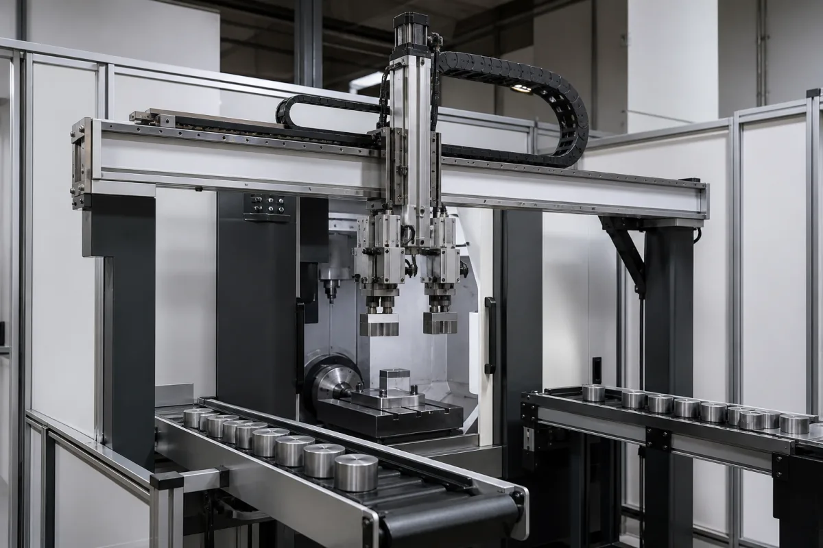
Representative product image. Confirm appearance and specifications with the manufacturer.

Product Specifications

Technical details and manufacturing context for Loading/Unloading Mechanism

Definition
The Loading/Unloading Mechanism is a mechanical system integrated within the Cooling and Quenching Unit. Its primary function is the controlled insertion of hot materials into the cooling/quenching chamber and the subsequent removal of processed materials. The mechanism ensures proper positioning, timing, and handling to maintain process efficiency and material integrity. It is designed to operate in coordination with the unit's control system, synchronizing loading and unloading with the cooling/quenching cycles. The mechanism typically employs mechanical arms, conveyors, lifts, or robotic systems that operate based on programmed sequences or sensor feedback. Movement is often achieved using pneumatic, hydraulic, or electric actuators. The mechanism is available in configurations using materials such as stainless steel, carbon steel, or aluminum alloy, with frame and contact parts commonly made from Q235B or 304 steel. Key parameters include a load capacity of 500–2000 kg per transfer cycle, a transfer speed of 0.1–0.5 m/s, positioning accuracy of ±0.5 mm, operating pressure of 0.6–0.8 MPa, operating temperature range of -10 to 60 °C, power supply of 220/380 V AC three-phase 50 Hz, motor power of 1.5–5.5 kW, ingress protection rating of IP54–IP65 (IEC 60529), and an approximate weight of 800–1500 kg. These values are reference ranges and must be confirmed for the specific model and application. The mechanism is a component intended for integration into a larger system; it is not a standalone product. For procurement, verify model-specific values and standards with the legal manufacturer or supplier.
Working Principle
The Loading/Unloading Mechanism operates based on a programmed sequence or sensor feedback, coordinating with the cooling unit's control system. It uses actuators (pneumatic, hydraulic, or electric) to drive mechanical arms, conveyors, or lifts. The mechanism inserts hot materials into the cooling chamber, holds them for the required duration, and then removes them. Positioning accuracy is maintained through sensors and mechanical guides. The system is designed to handle loads up to 2000 kg and operates within specified speed and pressure ranges. It is essential to verify the actual operating parameters for the specific configuration.
Common Materials
Stainless Steel, Carbon Steel, Aluminum Alloy
Technical Parameters
ParameterTypical rangeNotes & selection driver
Load Capacity500–2000 kgMaximum weight of material per transfer cycle
Transfer Speed0.1–0.5 m/sAdjustable for process requirements
Positioning Accuracy±0.5 mmEnsures proper alignment with cooling unit
Operating Pressure0.6–0.8 MPaPneumatic system pressure
Operating Temperature-10–60 °CAmbient temperature range
Power Supply220/380 V ACThree-phase, 50 Hz
Motor Power1.5–5.5 kWDepends on load and speed
Ingress ProtectionIP54–IP65Dust and water resistanceIEC 60529
MaterialQ235B/304Frame/contact partsGB/T 700
Weight800–1500 kgApproximate, depends on configuration

Ranges are indicative industry figures for RFQ preparation, not a supplier commitment. Confirm every value and standard with the legal manufacturer before ordering.

Components / BOM
  • Actuator Arm
    Primary component that physically moves materials into/out of the unit
    Material: Stainless Steel
  • Gripper/Clamp
    End-effector that securely holds materials during transfer
    Material: Heat-resistant Alloy
  • Guide Rails Part
    Provide precise linear movement path for the mechanism
    Material: Carbon Steel
  • Drive Motor
    Provides power for mechanism movement
    Material: Copper Windings, Steel Housing
  • Position Sensor
    Tells the control when the arm has reached the insert or extract position.

Industry Taxonomies & Aliases

Commonly used trade names and technical identifiers for Loading/Unloading Mechanism.

Applied To / Applications

This component is essential for the following industrial systems and equipment:

Industrial Ecosystem & Supply Chain Structure

Complementary Systems
Downstream Applications
Specialized Tooling

Application Fit & Sizing Matrix

Operational Limits
pressure: 0 to 10 bar
flow rate: Up to 50 m³/h
temperature: -20°C to 200°C
slurry concentration: Up to 40% solids by weight
Media Compatibility
✓ Steel pellets ✓ Mineral slurries ✓ Polymer granules
Unsuitable: Highly corrosive acidic environments (pH < 2)
Sizing Data Required
  • Material bulk density (kg/m³)
  • Required throughput capacity (tons/hour)
  • Material particle size distribution (mm)

Reliability & Engineering Risk Analysis

Failure Mode & Root Cause
Bearing fatigue failure
Cause: Cyclic loading from repeated start-stop cycles and shock loads during material transfer, leading to micro-cracking and eventual spalling.
Hydraulic cylinder seal degradation
Cause: Contamination from particulate matter in hydraulic fluid combined with high-pressure cycling, causing extrusion and wear of seals.
Maintenance Indicators
  • Unusual grinding or knocking noises during operation
  • Visible hydraulic fluid leaks at cylinder connections or actuator joints
Engineering Tips
  • Implement predictive maintenance with vibration analysis on rotating components and oil analysis on hydraulic systems
  • Install proper filtration systems for hydraulic fluid and establish regular lubrication schedules with appropriate greases

Indicative industry ranges for design and RFQ preparation. Confirm the exact figures and applicable standard with the manufacturer before specifying.

Compliance & Manufacturing Standards

Applicable Standards
ISO 12100:2010 - Safety of machinery ANSI B30.20 - Below-the-Hook Lifting Devices DIN 15020 - Cranes; principles relating to rope drives; calculation and construction

Quoted from the published standard.

Manufacturing Precision
  • Bore diameter: +/-0.05mm
  • Parallelism of mounting surfaces: 0.1mm
Quality Inspection
  • Load testing to 125% rated capacity
  • Magnetic particle inspection for surface cracks

Manufacturers of Loading/Unloading Mechanism

Manufacturer profiles associated with Loading/Unloading Mechanism.

Sourcing Loading/Unloading Mechanism from China?
Tell us your specification and target quantity — we will match it against manufacturer records and come back with the factories that fit.
Request manufacturers We manufacture this

Manufacturer listings support early research and capability understanding. They are not certification, ranking, or transaction guarantees.

Technical documentation
Request current drawings, revision history, and a signed specification sheet.
Manufacturing capability
Verify equipment lists, process limits, capacity, and representative production evidence.
Inspection readiness
Confirm test methods, calibrated equipment, sampling plans, and traceable reports.
Supplier transparency
Check the legal entity, factory address, ownership, certifications, and direct contacts.

CNFX does not score or rank suppliers. Buyers must verify all claims and documents with the legal manufacturer before ordering.

Supply Chain Compatible Machinery & Devices

Heavy-Duty CNC Plasma Cutting Machine

The Heavy-Duty CNC Plasma Cutting Machine is a standalone industrial device designed for cutting conductive metals such as steel, stainless steel, aluminum, and copper alloys.

Explore Specs →
Automated Powder Coating System

Integrated industrial system for applying dry powder coatings to metal substrates.

Explore Specs →
Centrifugal Pump Impeller

The centrifugal pump impeller is a critical rotating component that converts mechanical energy from the motor into kinetic energy in fluid systems.

Explore Specs →
High-Precision CNC Laser Cutting Machine

Computer-controlled industrial machine using focused laser beams to cut sheet metal with micron-level accuracy.

Explore Specs →

Frequently Asked Questions

What is the typical load capacity of this mechanism?

The load capacity is specified as 500–2000 kg per transfer cycle. This is a reference range; the actual capacity depends on the specific model and configuration. Always confirm with the manufacturer.

What materials are used in the construction?

The mechanism can be made from stainless steel, carbon steel, or aluminum alloy. Frame and contact parts are typically Q235B or 304 steel. Material selection depends on the application and environmental conditions.

What is the positioning accuracy?

The positioning accuracy is ±0.5 mm, ensuring proper alignment with the cooling unit. This value is a reference and should be verified for the specific model.

What are the electrical requirements?

The power supply is 220/380 V AC, three-phase, 50 Hz. Motor power ranges from 1.5 to 5.5 kW. These are reference values; check the nameplate and technical documentation for exact requirements.

Data Basis

Editorial classification, named public sources where available, and source-reviewed manufacturer records.

Preliminary Technical Classification
This page supports structured research, RFQ preparation, and supplier evaluation. It does not replace buyer-led supplier qualification, standards review, or technical approval.
Buyer enquiry

Request manufacturing insight for Loading/Unloading Mechanism

Ask for use case, specification boundaries, supplier type, and RFQ preparation information for this product.

Where it goes
Straight to the CNFX editorial desk, and to the manufacturer if this product is linked to a claimed profile. Nothing is broadcast to a supplier list.
Your details stay here
We do not sell or rent enquiry data, and we do not add you to a mailing list. Used only to answer this request.
No commission, no middleman
CNFX is a directory. We take no cut of any order and never negotiate on a supplier's behalf.
What we don't claim
A listing is not an endorsement. Qualify every supplier and verify every figure yourself before ordering.

Your business information is used only to process this request.

Thank you! Your message has been sent. We'll respond within 1–3 business days.
Sorry, we couldn't send your message. Please try again, or email us at contact@cnfx.com.

Need to Manufacture Loading/Unloading Mechanism?

Compare manufacturer profiles with relevant product and process capability.

Previous Product
Z-axis Ram/Spindle
Last Product
Get QuotesChat