Editorial Technical Reference

Cooling and Quenching Unit

This page explains how Cooling and Quenching Unit is classified within Machinery and Equipment Manufacturing. Technical values and manufacturer relationships are research references; confirm the current specification and supplier evidence for each order.

Technical Definition & Core Assembly

A specialized unit within forging/stamping lines that rapidly cools and hardens metal components through controlled quenching processes.
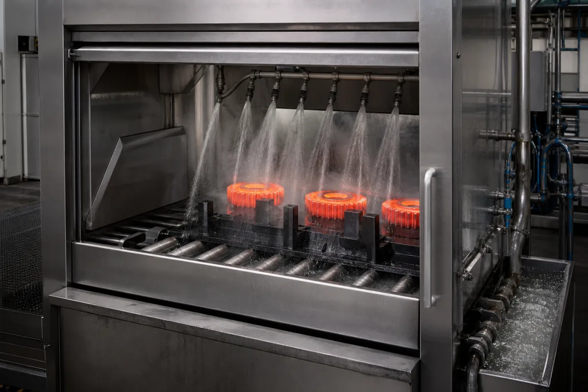
Representative product image. Confirm appearance and specifications with the manufacturer.

Product Specifications

Technical details and manufacturing context for Cooling and Quenching Unit

Definition
The Cooling and Quenching Unit is a critical component of the Automated Multi-Station Forging and Stamping Production Line. Its primary function is to rapidly reduce the temperature of hot forged or stamped metal parts using controlled quenching media, typically oil, water, or polymer solutions. This rapid heat extraction induces phase transformations in the metal's microstructure, such as the conversion of austenite to martensite in steels, resulting in increased hardness, strength, and wear resistance while minimizing distortion and residual stresses. The unit is designed to handle components with a quenching capacity of 500–2000 kg/h, accommodating a quenching temperature range of 800–1250 °C. Cooling rates can be precisely controlled between 5 and 150 °C/s, ensuring consistent part properties. Temperature uniformity is maintained within ±10 °C, adhering to AMS 2750 standards. The quenching medium flow rate ranges from 100 to 500 L/min, with a pressure of 0.2–0.6 MPa, ensuring proper agitation and coverage. The unit operates within an ambient temperature range of 10–50 °C and requires an electrical power supply of 50–200 kW at a voltage of 380–480 V AC (three-phase, 50/60 Hz) per IEC 60038. Control precision is ±1 °C, and the unit offers ingress protection rated IP54–IP65 per IEC 60529. The machine weight ranges from 5000 to 15000 kg, with a footprint of 3000×2000×2500 to 6000×3000×4000 mm. Constructed from stainless steel, carbon steel, and heat-resistant alloys, the unit is built for durability in demanding industrial environments. All listed parameters are reference ranges and must be verified with the legal manufacturer for specific models and applications.
Working Principle
Hot metal components from forging or stamping stations enter the Cooling and Quenching Unit, where they are submerged in or sprayed with quenching media at controlled temperatures and flow rates. The rapid heat extraction causes phase transformations in the metal, typically austenite to martensite in steels, resulting in hardened microstructures. Temperature sensors, flow controls, and agitation systems ensure uniform cooling rates throughout the component. The unit's control system maintains precise temperature and flow parameters, allowing for consistent quenching results. Operators can adjust cooling rates and medium flow to achieve desired mechanical properties. The process is critical for achieving the required hardness and strength in finished parts.
Common Materials
Stainless Steel, Carbon Steel, Heat-Resistant Alloys
Technical Parameters
ParameterTypical rangeNotes & selection driver
Quenching Capacity500–2000 kg/hDetermines throughput for production line
Quenching Temperature Range800–1250 °CHeating temperature before quenching
Cooling Rate5–150 °C/sCritical for hardness and microstructure
Temperature Uniformity±10 °CEnsures consistent part propertiesAMS 2750
Quenching Medium Flow Rate100–500 L/minAffects cooling uniformity
Quenching Medium Pressure0.2–0.6 MPaEnsures proper agitation and coverage
Operating Temperature Range10–50 °CAmbient temperature for equipment operation
Electrical Power50–200 kWTotal connected load
Supply Voltage380–480 V ACThree-phase, 50/60 HzIEC 60038
Control Precision±1 °CTemperature control accuracy
Ingress ProtectionIP54–IP65Protection against dust and waterIEC 60529
Machine Weight5000–15000 kgAffects installation and foundation
Footprint (L×W×H)3000×2000×2500–6000×3000×4000 mmSpace required for installation

Ranges are indicative industry figures for RFQ preparation, not a supplier commitment. Confirm every value and standard with the legal manufacturer before ordering.

Components / BOM
  • Quenching Tank
    Primary reservoir containing quenching medium
    Material: Stainless Steel
  • Agitation System
    Circulates quenching medium for uniform cooling
    Material: Stainless Steel
  • Temperature Control Unit
    Maintains precise quenching medium temperature
    Material: Copper, Stainless Steel
  • Loading/Unloading Mechanism
    Transfers components into and out of quenching zone
    Material: Carbon Steel
  • Fume Extraction System
    Removes vapors and fumes generated during quenching
    Material: Galvanized Steel
  • Flow Control
    Sets the quenching medium flow rate, one of the two things the operator adjusts to hit the target hardness.
  • Spray System Optional
    Applies quenching medium as spray instead of immersion, on the parts that call for it.

Industrial Ecosystem & Supply Chain Structure

Complementary Systems
Downstream Applications
Specialized Tooling

Application Fit & Sizing Matrix

Operational Limits
pressure: Up to 10 bar (system operating pressure)
flow rate: 50-5000 L/min (coolant circulation capacity)
temperature: Ambient to 1200°C (quenching media temperature range)
slurry concentration: Up to 30% solids by weight (for slurry quenching applications)
Media Compatibility
✓ Water-based polymer quenchants ✓ Oil-based quenching media ✓ High-pressure water mist systems
Unsuitable: Chloride-containing environments (risk of stress corrosion cracking)
Sizing Data Required
  • Component mass and material type (steel grade, aluminum, etc.)
  • Required cooling rate (C°/second) and final hardness specification
  • Production throughput (parts/hour) and component dimensions

Reliability & Engineering Risk Analysis

Failure Mode & Root Cause
Corrosion and scaling
Cause: Chemical attack from process fluids, water impurities, or improper pH levels leading to material degradation and reduced heat transfer efficiency.
Pump and impeller failure
Cause: Cavitation due to low suction pressure, improper NPSH, or wear from abrasive particles in the quenching medium.
Maintenance Indicators
  • Unusual vibration or noise from pumps and motors indicating bearing wear or cavitation
  • Visible leaks, discoloration, or scaling on heat exchanger surfaces and piping connections
Engineering Tips
  • Implement regular water quality monitoring and treatment to control pH, hardness, and chemical composition of quenching fluids
  • Establish predictive maintenance with vibration analysis and thermal imaging to detect early-stage mechanical and thermal inefficiencies

Indicative industry ranges for design and RFQ preparation. Confirm the exact figures and applicable standard with the manufacturer before specifying.

Compliance & Manufacturing Standards

Applicable Standards
ASME B31.3 - Process piping DIN EN 13445 - Unfired pressure vessels

Quoted from the published standard.

Manufacturing Precision
  • Flow rate accuracy: +/- 2% of rated capacity
  • Temperature control: +/- 1.5°C across all zones
Quality Inspection
  • Pressure test (hydrostatic/pneumatic) per ASME BPVC Section VIII
  • Material verification via PMI (Positive Material Identification)

Manufacturers of Cooling and Quenching Unit

Manufacturer profiles associated with Cooling and Quenching Unit.

Sourcing Cooling and Quenching Unit from China?
Tell us your specification and target quantity — we will match it against manufacturer records and come back with the factories that fit.
Request manufacturers We manufacture this

Manufacturer listings support early research and capability understanding. They are not certification, ranking, or transaction guarantees.

Technical documentation
Request current drawings, revision history, and a signed specification sheet.
Manufacturing capability
Verify equipment lists, process limits, capacity, and representative production evidence.
Inspection readiness
Confirm test methods, calibrated equipment, sampling plans, and traceable reports.
Supplier transparency
Check the legal entity, factory address, ownership, certifications, and direct contacts.

CNFX does not score or rank suppliers. Buyers must verify all claims and documents with the legal manufacturer before ordering.

Supply Chain Compatible Machinery & Devices

Hydraulic Press

Industrial machine using hydraulic pressure to compress, form, or assemble materials

Explore Specs →
Heavy-Duty CNC Plasma Cutting Machine

The Heavy-Duty CNC Plasma Cutting Machine is a standalone industrial device designed for cutting conductive metals such as steel, stainless steel, aluminum, and copper alloys.

Explore Specs →
Automated Powder Coating System

Integrated industrial system for applying dry powder coatings to metal substrates.

Explore Specs →
Centrifugal Pump Impeller

The centrifugal pump impeller is a critical rotating component that converts mechanical energy from the motor into kinetic energy in fluid systems.

Explore Specs →

Frequently Asked Questions

What is the purpose of a Cooling and Quenching Unit?

It rapidly cools hot forged or stamped metal parts to achieve desired hardness and mechanical properties through controlled quenching.

What quenching media can be used?

Typically oil, water, or polymer solutions, depending on the material and required properties.

How is cooling rate controlled?

Through temperature sensors, flow controls, and agitation systems that maintain uniform cooling rates within a specified range.

What standards apply to this unit?

Relevant standards include AMS 2750 for temperature uniformity, IEC 60038 for voltage, and IEC 60529 for ingress protection. Verify compliance with the manufacturer.

Data Basis

Editorial classification, named public sources where available, and source-reviewed manufacturer records.

Preliminary Technical Classification
This page supports structured research, RFQ preparation, and supplier evaluation. It does not replace buyer-led supplier qualification, standards review, or technical approval.
Buyer enquiry

Request manufacturing insight for Cooling and Quenching Unit

Ask for use case, specification boundaries, supplier type, and RFQ preparation information for this product.

Where it goes
Straight to the CNFX editorial desk, and to the manufacturer if this product is linked to a claimed profile. Nothing is broadcast to a supplier list.
Your details stay here
We do not sell or rent enquiry data, and we do not add you to a mailing list. Used only to answer this request.
No commission, no middleman
CNFX is a directory. We take no cut of any order and never negotiate on a supplier's behalf.
What we don't claim
A listing is not an endorsement. Qualify every supplier and verify every figure yourself before ordering.

Your business information is used only to process this request.

Thank you! Your message has been sent. We'll respond within 1–3 business days.
Sorry, we couldn't send your message. Please try again, or email us at contact@cnfx.com.

Need to Manufacture Cooling and Quenching Unit?

Compare manufacturer profiles with relevant product and process capability.

Previous Product
Coolant System
Next Product
Cooling Heat Exchanger or Chiller Unit
Get QuotesChat