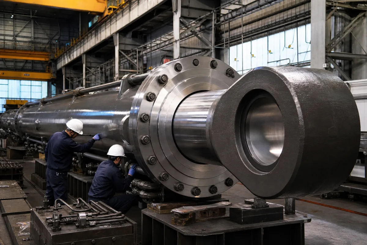
Main cylinder for hydraulic presses: prefilling it for fast approach and decompressing it before the return stroke
Main cylinders of large hydraulic presses · Prefilling the cylinder from the tank through a prefill valve for fast approach, closing it for the pressing stroke, and decompressing the stored energy in oil and frame before the ram returns
This page covers the main cylinder of large hydraulic presses, the cylinder whose ram delivers the press force, as a hydraulic unit with its prefill valve and decompression: filled from an overhead or adjacent tank during fast approach, pressurised by pumps for the working stroke, and relieved before return. Ask three things first: how the cylinder is filled during fast approach and at what flow, how the prefill valve is closed, monitored and opened, and how the stored pressure is released before the ram goes back up.
Main cylinders of hydraulic presses with their prefill (filling) valves and decompression control. Open-die forging presses, extrusion presses, stamping presses and body panel presses as complete machines are covered on their own pages, single-acting rams on the Hydraulic ram page, general cylinders on the Hydraulic cylinder page air-over-oil intensifiers on their own page, and proportional pressure control on the Hydraulic pressure control system for presses page. Pumps, accumulators and press frames sold alone are outside this page.
CNFX editorial research · Sources checked October 12, 2026 · 4 sources
Prefilling: the tank fills the cylinder while the ram falls, then the valve closes for the pressing stroke
A Cincinnati Incorporated patent on hydraulic press control describes the slide moving down with the valve to the upper volume closed, so a vacuum forms in the cylinder's upper annular volume; at a set figure, for example 3 psig, a light spring is overcome, the main poppet of the prefill valve opens and atmospheric pressure pushes oil from the reservoir into the cylinder. In its example about three times as much oil enters this way as the high- and low-volume pumps deliver, giving a very fast approach before the workpiece is contacted while making sure the upper volume is full for the working stroke. [1]
Hauhinco describes its prefill valves, DN80 to DN260, as giving large flow cross-sections for fast low-pressure positioning, primarily on press cylinders, and staying closed during the high-pressure stroke; each has a valve piston, seat, control piston and single- or multi-stage electrohydraulic pilot, with stainless steel or bronze parts and proximity switches that monitor the switching points of the valve piston. [2]
Editorial calculation, with assumed figures: a 1 m diameter ram (0.785 m²) approaching at 300 mm/s displaces about 0.236 m³/s, or about 14,100 L/min, the order of flow that Rexroth's SF300 prefill valve is listed to pass at 15,600 L/min with 0.3 bar differential pressure. [3]
Give the supplier the press force, ram diameter and stroke, fast-approach, pressing and return speeds, the pump flows, the tank position, the fluid (mineral oil or water-based), the cycle rate, and how the press control will time prefill, pressing and decompression.
02
Decompression: releasing the energy stored in the oil and the frame before the ram reverses
The same Cincinnati patent explains that when the press is heavily loaded, considerable energy is stored in the frame and the hydraulic fluid, so its control sets a total decompression time that increases with system pressure, using an empirical constant for the particular press and hydraulic system, to relieve the pressure and stored energy gradually and prevent shock and noise; it adds that adapting decompression to the load prevents surges, noise and equipment damage and increases production speed. [1]
Listings for Rexroth's SF prefill valves describe them as pilot-operated check valves that let oil into the cylinder during prefill and block reverse flow until a pilot signal opens them, with pre-decompression to relieve trapped pressure before full opening; the SF300 weighs 625 kg and is fixed with 24 M42 screws at 4,500 Nm. [3][4] Editorial note: the pilot oil volume needed to open the valve, 687 cm³ on the SF300, sets how fast the pilot circuit can open it on large presses.
1 company lists this product among what they make. Company figures are quoted from each
company's own website; every card states where the relationship came from.
Huanan Heavy Industry Technology Co., Ltd.
Manufacturing site to be confirmed for the order
Builds aluminium and copper extrusion presses and lists a main cylinder among its products.
Explore company information and manufacturing capabilities, then discuss the scope of your project with a relevant supplier.
Share this page
Compiled and source-reviewed by the CNFX editorial team.
Each manufacturer above links to the page on that company's own website where the product is listed, with the date we checked it. How we source and review
· Page last updated 13 October 2026
Buyer questions
How does a hydraulic press main cylinder fill so fast during approach?
A Cincinnati patent describes vacuum in the cylinder opening a prefill valve at about 3 psig so oil flows in from the reservoir, about three times the pumps' delivery in its example. [1]
Why must a press main cylinder be decompressed before the return stroke?
Under heavy load energy is stored in the frame and oil; releasing it gradually, over a time that rises with pressure, prevents shock and noise. [1]
How large are prefill valves for big presses?
Rexroth's SF300 is listed at 15,600 L/min at 0.3 bar with a 63 mm poppet stroke; Hauhinco offers DN80 to DN260. [3][2]
Sources and what still needs a direct check
Sources checked 2026-10-12. A Cincinnati Incorporated patent explains prefill and decompression control; Hauhinco describes its prefill valves; a distributor lists Rexroth SF prefill valve data.