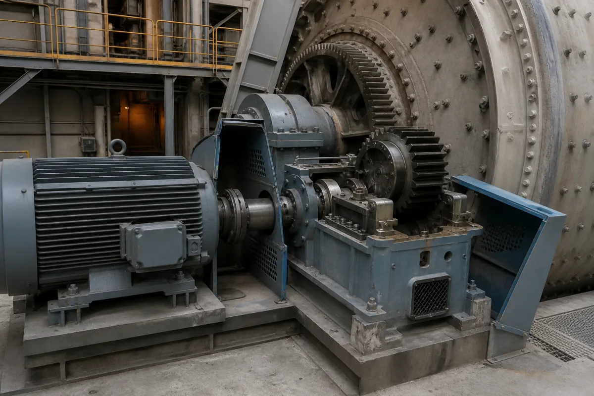
Main drive system of a fertilizer drum granulator: choosing the drive type, the drum speed and its adjustment range for the rolling bed
Fertilizer drum granulators · drum speed as a share of critical speed, 11 kW to 90 kW motors from Ø1.4 m to Ø2.8 m drums, chain, girth gear, friction or direct drive, variable-speed range
A granulation drum earns its product from the way the bed rolls, and the bed rolls the way the drum is turned. The main drive of a fertilizer granulator therefore has to do more than deliver torque: it fixes the drum speed, and with a variable-speed motor or frequency converter it also sets how far that speed can be moved while operators adjust granule growth. When buying one, settle three things: which final drive suits the drum's power and size, what drum speed the process needs relative to the drum's critical speed, and how far, and by what means, that speed has to be adjustable.
Main drives of rotary drum granulators for compound, phosphate and organic fertilizers seen from the drum's duty: choice of final drive (chain and sprocket, girth gear and pinion, friction drive through the trunnion wheels, or direct shaft drive), drum speed and its relation to critical speed, motor power against drum size, overall reduction from motor to drum, and variable-speed control. Girth gear drive trains as heavy machinery, with power per pinion, dual pinions, auxiliary drives and gear materials for mills, kilns and dryers, are covered on the Drive system (girth gear drive train) page; split-housing ZQ, JZQ and ZSY reducers on the Split-housing parallel-shaft cylindrical gear reducer page; enclosed helical reducers on the Gear reduction unit page; geared motors for powder blenders on the Blender drive motor page. The granulator drum, its bed, slurry and ammonia feeds are covered on the Rotary drum granulator for compound fertilizers page, and the welded shell on the Rotating drum shell page.
CNFX editorial research · Sources checked October 13, 2026 · 5 sources
Chain and sprocket up to 55 kW, girth gear and pinion above it, friction drive on drums of about 1.8 m and under
FEECO, which builds granulation drums and other rotary drums, sorts its drive assemblies by the power the drum needs. Chain and sprocket drives are reserved for smaller drums running up to 75 hp (55 kW) and are not suitable above it; gear and pinion drives are offered for heavy-duty drums above 75 hp, cost more, and in FEECO's words operate and wear better in demanding applications. [1]
The other two arrangements avoid a gear or sprocket around the shell. A friction drive turns two of the four trunnion wheels, joined by one shaft, through a shaft-mounted reducer and motor, and FEECO places it on low-power drums of about 6 ft (1.8 m) and under. A direct drive mounts a shaft on a solid discharge end plate and couples the motor and reducer to it; FEECO lists it for small to medium drums with motors up to 75 hp. For higher torque, a reducer can be added to the chain and gear drives to bring the motor speed down. [1]
A Chinese maker's granulator table shows where fertilizer drums sit on that scale. Zhengzhou Dynnor lists motors of 11 kW for a Ø1.4 × 4 m drum, 15 kW for Ø1.6 × 6 m and Ø1.8 × 6 m, 30 kW for Ø2.0 × 7 m, 37 kW for Ø2.2 × 8 m, 55 kW for Ø2.4 × 8 m and 90 kW for Ø2.8 × 8 m, with JZQ500 and JZQ650 reducers on the smaller drums and ZL750 and ZLY315 reducers on the two largest. [3] Editorial calculation against FEECO's split: every drum in that table up to Ø2.4 × 8 m is listed with no more than 55 kW, inside the chain-drive range, while the 90 kW Ø2.8 × 8 m drum is above it, in gear-and-pinion territory. [1][3]
Jiangsu Pengfei's Ø2.0 × 18 m granulating and cooling drum for sodium silicate shows a girth-gear drive in its parts list: girth gear and tyres in ZG45 cast steel, a 40Cr pinion, a ZSY224 reducer with a 22.4 ratio, and a 37 kW YCT315-4A motor, on two supports with a thrust roller. [4]
Give the drive supplier the drum diameter and length, the loaded mass and fill, the drum speed and its range, the motor power the drum maker has calculated, and whether chain, girth gear, friction or direct drive is preferred for the plant's maintenance practice.
02
Drum speed at 25–42 % of critical speed, and a 10:1 adjustable range from motor to drum
FEECO ties granulation to the rolling action of the bed: in a drum that turns too slowly the granules do not tumble enough to grow, and in one that turns too fast the material is carried round instead of tumbling. It sets that action through drum speed together with percent fill, and names an electronic variable frequency device (VFD) for controlling drum speed. [2]
Editorial calculation: critical speed is taken here as the speed at which centrifugal force on a particle at the top of the shell equals gravity, n_c = (60 / 2π) × √(2g / D) ≈ 42.3 / √D r/min with D the inner diameter in metres; this gives about 35.7 r/min for a 1.4 m drum, 29.9 r/min for 2.0 m and 25.3 r/min for 2.8 m, and the right-hand column divides each listed speed by that figure. [3][4]
A doctoral study at the Federal University of Uberlândia granulated single superphosphate in a rotating drum and reported a drum rotation of 38 % of critical speed, a recycle ratio of about 1:1, a granulation time of about 4–5 min and a drum fill of about 11 % among the conditions that worked well. [5] Editorial calculation: 38 % of the critical speed of a 2.0 m drum is about 11.4 r/min, close to the 10.8 r/min Dynnor lists for its Ø2.0 × 7 m granulator. [5][3]
Pengfei's drum shows how a speed range passes down the drive: the motor is listed at 1,320–132 r/min, the reducer at a ratio of 22.4, and the drum at 0.916–9.16 r/min. [4] Editorial calculation: 1,320 / 22.4 ≈ 58.9 r/min at the reducer output, so the pinion and girth gear stage reduces about 6.4 times more to reach 9.16 r/min, and both ends of the range give the same ratio, a 10:1 speed range carried straight through to the drum.
State the drum speed the process trials found, the lowest and highest speeds the operators need, how the speed is varied (frequency converter or another variable-speed motor), and whether the drive must also inch or turn the loaded drum slowly for inspection.
03
Drum and process data for a granulator main drive
Paste it into your enquiry below or into an email to a maker, then replace every bracket.
Drum: [inner diameter; length; slope; loaded mass; fill %]
Product: [NPK, phosphate, organic or other; bulk density]
Speed: [design r/min; minimum and maximum; share of critical speed]
Power: [motor kW from the drum maker; starting duty]
Final drive: [chain and sprocket, girth gear and pinion, friction or direct]
Reducer: [type and ratio; mounting]
Speed control: [frequency converter or other; inching or slow turning]
Site: [supply voltage; dust and wash-down conditions]
Explore company information and manufacturing capabilities, then discuss the scope of your project with a relevant supplier.
Share this page
Compiled and source-reviewed by the CNFX editorial team.
Each manufacturer above links to the page on that company's own website where the product is listed, with the date we checked it. How we source and review
· Page last updated 13 October 2026
Buyer questions
Which drive type suits a fertilizer granulation drum?
FEECO uses chain and sprocket drives on drums up to 75 hp (55 kW), gear and pinion drives above that, and friction drives through the trunnion wheels on low-power drums of about 1.8 m and under. [1]
How fast does a fertilizer drum granulator turn?
Zhengzhou Dynnor lists 15.05 r/min for a Ø1.4 × 4 m drum down to 6.5 r/min for a Ø2.8 × 8 m drum; a superphosphate study at the Federal University of Uberlândia reported 38 % of critical speed as a good working condition. [3][5]
How is the drum speed of a granulator adjusted?
FEECO names an electronic variable frequency device (VFD) for controlling drum speed; Jiangsu Pengfei lists a variable-speed motor of 1,320–132 r/min giving its drum 0.916–9.16 r/min. [2][4]
How much motor power does a drum granulator need?
Zhengzhou Dynnor's table runs from 11 kW for a Ø1.4 × 4 m drum to 90 kW for a Ø2.8 × 8 m drum. [3]
Sources and what still needs a direct check
Sources checked 2026-10-13. FEECO, a US builder of rotary drums, on drive assembly types and on how drum speed sets the rolling bed; two Chinese makers' published drum specifications (Zhengzhou Dynnor's granulator table and Jiangsu Pengfei's granulating and cooling drum); and a doctoral thesis from the Federal University of Uberlândia on superphosphate drum granulation.