Editorial Technical Reference

Position Feedback Sensors

This page explains how Position Feedback Sensors is classified within Machinery and Equipment Manufacturing. Technical values and manufacturer relationships are research references; confirm the current specification and supplier evidence for each order.

Technical Definition & Core Assembly

Position feedback sensors are critical components in robotic part handlers that continuously monitor and report the precise position, angle, or displacement of robotic joints, end-effectors, or moving parts.
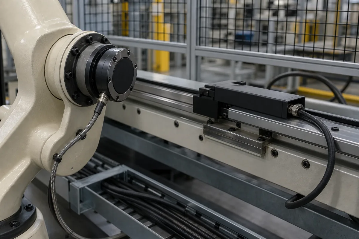
Position Feedback Sensors in a manufacturing environment
Representative product image. Confirm appearance and specifications with the manufacturer.

Product Specifications

Technical details and manufacturing context for Position Feedback Sensors

Definition
Position feedback sensors are a broad functional family that reports linear or angular position to a controller. It includes unlike devices such as incremental or absolute encoders, resolvers, LVDTs, potentiometric transducers and some magnetic, optical, inductive or capacitive sensors. These technologies do not share one measurement range, resolution, output, supply, temperature range, enclosure, material, shock/vibration limit, mass or MTBF. The values on this page are directory comparison prompts rather than one sensor specification. Select the sensor technology and exact model from the motion, range, accuracy and repeatability requirement; dynamic response; interface and diagnostic needs; mechanical coupling and alignment; environment, cable/connector and installation; and any required safety function. Confirm every value with a current manufacturer data sheet, drawing, test condition and certificate where applicable.
Working Principle
Position feedback sensors operate by detecting physical changes in position using technologies like optical, magnetic, capacitive, or resistive methods. They convert these changes into electrical signals, which are then processed by the robot's control system. The control system compares the actual position with the target position, enabling precise motion control and error correction. Common sensor types include encoders, resolvers, potentiometers, and LVDTs, each with specific advantages depending on the application requirements.
Common Materials
Model-specific housing and flange materials, Technology-specific sensing element and electronic materials, Model-specific connector, cable and sealing materials, Shaft, bearing, target or scale materials where the selected design uses them
Technical Parameters
ParameterTypical rangeNotes & selection driver
Measurement Range0–100 mmStandard range; custom ranges available
Resolution0.01 mmHigher resolution available on request
Linearity±0.05 % FSFull scale; better linearity on premium models
Output Signal4–20 mAAnalog current loop; other outputs available
Supply Voltage9–36 V DCReverse polarity protected
Operating Temperature-40–85 °CExtended temperature range optional
Ingress ProtectionIP54–IP67IP67 for washdown environmentsIEC 60529
Material316LStainless steel for corrosion resistance
Weight0.2–0.5 kgDepends on cable length and options
Shock Resistance50 gHalf-sine, 11 msIEC 60068-2-27
Vibration Resistance20 g10–2000 HzIEC 60068-2-6
MTBF50000 hCalculated per Telcordia SR-332

Ranges are indicative industry figures for RFQ preparation, not a supplier commitment. Confirm every value and standard with the legal manufacturer before ordering.

Components / BOM
  • Sensor Element Part
    Detects position changes through physical interaction
    Material: Optical glass, magnetic strips, or resistive film
  • Signal Processor
    Converts raw sensor data into usable electrical signals
    Material: Silicon semiconductor
  • Housing Part
    Protects internal components from environmental factors
    Material: Aluminum alloy or stainless steel
  • Connector Interface
    Provides electrical connection to control system
    Material: Plastic housing with gold-plated contacts
  • Mounting Bracket Part
    Secures sensor to robotic structure
    Material: Steel or aluminum

Application & selection

Application Fit & Sizing Matrix

Operational Limits
motion: Choose linear/rotary, absolute/incremental, single-turn/multi-turn and contact/contactless technology for the actual travel and cycle.
safety: If used in a safety function, define the required function and PLr/SIL architecture and select a device with matching safety data.
interface: Specify supply, signal/protocol, update rate, diagnostics, connector/cable, grounding/shielding and controller compatibility.
metrology: Define accuracy, repeatability, resolution, linearity, hysteresis, latency/bandwidth and an error budget at relevant speed and temperature.
mechanical: Specify shaft, coupling, target/scale, alignment, runout, mounting, permissible loads and motion overtravel.
environment: Specify temperature, ingress exposure, cleaning chemical, pressure/immersion only if real, shock/vibration profile, EMC and hazardous area.
Sizing Data Required
  • Map the controlled motion and required uncertainty
  • Choose sensing technology before comparing numeric ranges
  • Verify mechanical/electrical interfaces and dynamic behaviour
  • Define environmental tests with complete severities and acceptance criteria
  • Validate the installed loop and record calibration/commissioning baselines

Risk, maintenance & compliance

Reliability & Engineering Risk Analysis

Failure Mode & Root Cause
Signal drift or loss
Cause: Electrical noise interference, connector corrosion, or internal component degradation from thermal cycling
Mechanical binding or jamming
Cause: Contamination ingress (dust, moisture, oil), wear of moving parts, or misalignment from vibration
Maintenance Indicators
  • Erratic or intermittent position readings during operation
  • Unusual audible grinding or clicking noises during sensor movement
Engineering Tips
  • Implement regular cleaning and inspection schedules to prevent contamination buildup, using appropriate seals or enclosures for harsh environments
  • Ensure proper electrical grounding and shielding to minimize electromagnetic interference, and verify mounting alignment to reduce mechanical stress

Indicative industry ranges for design and RFQ preparation. Confirm the exact figures and applicable standard with the manufacturer before specifying.

Compliance & Manufacturing Standards

Applicable Standards
IEC 60529 classifies enclosure ingress protection; require the exact-model code and installed connector/cable state, and specify cleaning or chemical compatibility separately. ASTM A240/A240M-26 covers stainless steel plate, sheet and strip. It does not certify a complete sensor, shaft, housing, seal, connector or corrosion performance, so its citation was removed from the generic 316L parameter. IEC 60068-2-27:2008 and IEC 60068-2-6:2007 provide procedures for specified shock and sinusoidal-vibration severities. They do not specify a universal 50 g/11 ms or 20 g/10–2000 Hz product rating. IEC 60947-5-2:2019 applies to specified proximity-switch technologies, not all encoders, resolvers, LVDTs or potentiometric sensors. IEC 61131-2:2017 applies to PLC/PAC industrial-control equipment and associated peripherals, not automatically to every sensor. ISO 13849-1:2023 is a methodology for safety-related parts of control systems; it neither assigns a required PLr to this application nor makes a generic sensor safety-rated.

Quoted from the published standard.

Manufacturing Precision
  • No universal 0.01 mm repeatability, ±0.05% FS linearity, SNR 20 dB, 0.5° alignment, 5 g RMS, 25 µm disk eccentricity, 100 Ω termination or MTBF 50,000 h is asserted. Define terms, conditions, uncertainty and acceptance per selected technology/model.
Quality Inspection
  • Verify model identity, sensing technology, data sheet/revision and the exact range/error/interface option.
  • Bench-check output, direction, zero/index, repeatability, hysteresis and dynamic response under defined motion, supply, load and temperature.
  • Inspect mounting/alignment, target/scale/coupling, cable/connector/seals and execute only the specified environmental/EMC/safety validation.
Technical documentation
Request current drawings, revision history, and a signed specification sheet.
Manufacturing capability
Verify equipment lists, process limits, capacity, and representative production evidence.
Inspection readiness
Confirm test methods, calibrated equipment, sampling plans, and traceable reports.
Supplier transparency
Check the legal entity, factory address, ownership, certifications, and direct contacts.

Compare the published product scope and source details, then include your specifications and quantity in an enquiry.

Manufacturers of Position Feedback Sensors

Manufacturer profiles associated with Position Feedback Sensors.

Sourcing Position Feedback Sensors from China?
Tell us your specification and target quantity — we will match it against manufacturer records and come back with the factories that fit.
Request manufacturers We manufacture this

Explore company information and manufacturing capabilities, then discuss the scope of your project with a relevant supplier.

Buyer enquiry

Request manufacturing insight for Position Feedback Sensors

Ask for use case, specification boundaries, supplier type, and RFQ preparation information for this product.

Where it goes
Straight to the CNFX editorial desk, and to the manufacturer if this product is linked to a claimed profile. Nothing is broadcast to a supplier list.
Your details stay here
We do not sell or rent enquiry data, and we do not add you to a mailing list. Used only to answer this request.
No commission, no middleman
CNFX is a directory. We take no cut of any order and never negotiate on a supplier's behalf.
What to include
Share your product specifications, quantity, destination and target delivery date.

Your business information is used only to process this request.

Thank you! Your message has been sent. We'll respond within 1–3 business days.
Sorry, we couldn't send your message. Please try again, or email us at [email protected].

Frequently Asked Questions

Is 4–20 mA the standard output for every position sensor?

No. Output can be analogue current/voltage, incremental pulses, absolute serial data, resolver signals or a vendor/fieldbus interface. Match electrical levels, protocol, update rate, diagnostics, cable and controller input to the exact model.

Do the listed range, resolution and linearity describe one sensor?

No. Linear and rotary technologies use different measurands and error definitions. Require the model-specific range, resolution, accuracy, repeatability, linearity, hysteresis and test conditions that matter to the control loop.

Does IP67 mean the sensor is suitable for washdown or chemical exposure?

No. IEC 60529 classifies enclosure protection under defined ingress tests. It does not by itself prove high-pressure cleaning, steam, corrosion, connector/cable sealing in the installed state or compatibility with a cleaning chemical.

Do IEC 60068-2-27 and IEC 60068-2-6 establish 50 g and 20 g ratings?

No. They provide shock and sinusoidal-vibration test procedures. Severity, pulse or sweep, axes, mounting, duration, operating state and acceptance criteria must come from the relevant product specification and model report.

Related equipment

Applied To / Applications

This component is essential for the following industrial systems and equipment:

Industrial Ecosystem & Supply Chain Structure

Data Basis

Editorial classification, named public sources where available, and source-reviewed manufacturer records.

Preliminary Technical Classification
This page supports structured research, RFQ preparation, and supplier evaluation. It does not replace buyer-led supplier qualification, standards review, or technical approval.

Need to Manufacture Position Feedback Sensors?

Compare manufacturer profiles with relevant product and process capability.

Previous Product
Position Encoders
Next Product
Position feedback system
Get QuotesChat