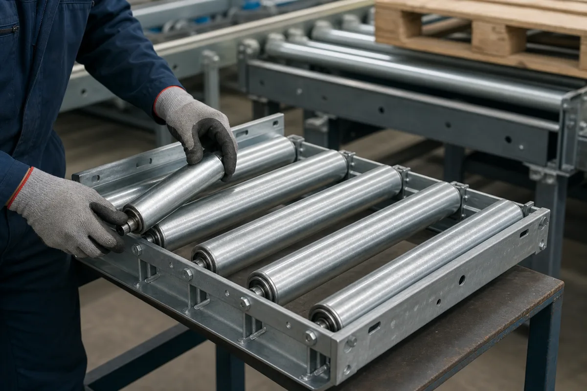
The rollers that drop into a conveyor frame · spring-loaded shafts that snap into bored side frames, female-threaded shafts bolted in so the rollers tie the frame together, load capacity that falls with installation length, ordering length against the clear width between frames
A roller conveyor section is a pair of bored side frames with rollers fitted across them. How each roller's shaft is held — sprung into the bores or bolted through them — decides how quickly rollers can be changed and whether they help hold the frame square, and the tube, shaft and length together set how much load each roller may carry.
Free-running conveyor rollers with their shafts and bearings, fitted between the side frames of unit-load roller conveyors. Complete pallet conveyors are covered on the Pallet conveyor (roller and chain conveyors for loaded pallets) page; transfers and turntables on the Pallet conveyor system transfer modules (chain transfers, roller transfers and turntables that turn pallets through 90° between conveyor lines) page; drum conveyors on the Drum conveyor: a powered roller conveyor for upright 200-litre steel drums, sized by roller pitch and roller load page; belt-conveyor drums on the Conveyor belt roller: drive and end drums with screw take-up for flat-belt conveyors page; chain drives on the Power transmission by roller chain and sprockets for machines and conveyors page.
01
Dugom's unit handling catalogue (a Rulmeca group brand) describes the shaft as the element that connects the rollers to the conveyor frame, "which generally consists of two parallel bored channels". The simplest version, for light rollers, holds the shaft axially with a spring inside the roller so it can be snapped into bored frames; the frame bores must be 0.5 mm larger than the shaft. [3]
For medium and heavy loads Dugom uses a tapped shaft screwed to the frame, and states that "In this case the shafts of the rollers act as a tie and contribute to the frame rigidity." [3]
Interroll orders spring-loaded rollers by a reference length: in its example, a conveyor with 500 mm clear width (installation length EL) takes a roller with RL = EL − 10 = 490 mm, with 0.5 mm axial play per side already allowed. For its female-threaded heavy rollers the installation length is RL + 10 mm. [2] [1]
Give the supplier the clear width between side frames, the bore or slot in the frame, and whether rollers must be changed without tools or bolted to stiffen the frame.
02
Interroll's Series 1700 catalogue page states that "The load capacity depends on the shaft version, the tube diameter and the length of the roller." Its table gives the maximum load per roller against installation length from 200 to 1,600 mm. [2]
The current Series 1700 heavy data sheet (01/2026) gives a maximum of 3,000 N, 2 m/s and −30 to +40 °C, but its load table applies from −5 to +40 °C, with a maximum static load of 600 N from −30 to −6 °C. Its female-thread figures for 50 × 1.5 mm tube differ slightly from the older catalogue page: 1,760 N against 1,770 N at 800 mm, 655 N against 660 N at 1,300 mm and 430 N against 440 N at 1,600 mm; use the data sheet that matches the roller ordered. [1] [2]
| Interroll Series 1700, steel tube | 200 mm | 600 mm | 1,000 mm | 1,600 mm | Source |
|---|---|---|---|---|---|
| 50 × 1.5, 10 mm spring-loaded shaft | 1,800 N | 560 N | 340 N | 220 N | [2] |
| 50 × 1.5, 12 mm spring-loaded shaft | 2,000 N | 1,200 N | 760 N | 520 N | [2] |
| 50 × 1.5, 11 mm hex spring-loaded | 2,000 N | 1,020 N | 640 N | 440 N | [2] |
| 50 × 1.5, 17 mm female thread | 3,000 N | 3,000 N | 1,120 N | 440 N (430 N in heavy data sheet) | [2] [1] |
| 60 × 3.0, 17 mm female thread | 3,000 N | 3,000 N | 3,000 N | 1,400 N (1,405 N in heavy data sheet) | [2] [1] |
Work out the load each roller carries from the heaviest unit, its contact length and the roller pitch, and ask the supplier for the table that applies to the tube, shaft and installation length offered.
03
Paste it into your enquiry below or into an email to a maker, then replace every bracket.
Frame: [clear width; bore or slot; hex or round] Shaft: [spring-loaded; female thread; hex; diameter] Tube: [diameter × wall; steel; stainless; sleeve] Load: [per roller; heaviest unit; pitch] Speed: [m/s] Temperature: [min; max] Quantity: [per section; spares]
Manufacturer profiles associated with Roller Assembly.
Explore company information and manufacturing capabilities, then discuss the scope of your project with a relevant supplier.
Interroll's tables show capacity falling with installation length; a 50 × 1.5 mm roller on a 10 mm spring-loaded shaft drops from 1,800 N at 200 mm to 220 N at 1,600 mm. [2]
Dugom recommends tapped shafts for medium and heavy loads; bolted rollers act as ties that stiffen the frame. [3]
0.5 mm larger than the shaft, according to Dugom. [3]
For Interroll spring-loaded rollers, the clear width between frames minus 10 mm. [2]
Sources checked 2026-10-13. Interroll publishes its Series 1700 heavy data sheet and an earlier Series 1700 catalogue page (hosted by ChipDip); Dugom Rulli publishes its unit handling catalogue (hosted by Tecnica Industriale).
Ask for use case, specification boundaries, supplier type, and RFQ preparation information for this product.
Compare manufacturer profiles with relevant product and process capability.