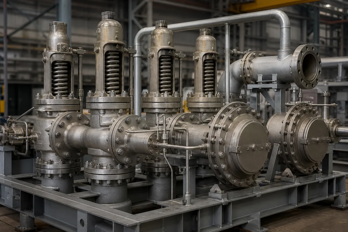
Boiler safety relief system: setting two or more safety valves on one steam generator, proving their combined capacity, and arranging drum, superheater and drain connections
Two or more safety valves protecting one steam boiler as a system · staggered set pressures within 3 % above MAWP and a 10 % band, total capacity that holds accumulation to 6 %, superheater valves that open before the drum valves, and the drains, sizes and tests around them
A single safety valve is a component. A steam boiler is protected by a set of them, drum and superheater, with set pressures, capacities and drains that have to work together: one valve opens first, the others follow in a planned order, and between them they must pass everything the boiler can generate without the pressure rising more than a few percent.
The arrangement of two or more safety valves and safety relief valves on one fired steam boiler or bank of boilers: the order and spread of their set pressures, their combined relieving capacity against the boiler's steaming rate, drum and superheater valve settings, inlet size, body drains and drain headers, gags, and setting and test routines, as laid down in US Coast Guard and Federal Railroad Administration rules and a valve maker's summary of the ASME code. The individual spring-loaded or pilot-operated relief valve, its set pressure tolerance, back pressure, piping losses and seat tightness, is covered on the Pressure relief valve page; replacement discs and seats on the Pressure relief valve disc and seat assembly page; hygienic and tank breather valves have their own pages. Unfired pressure vessels and heating boilers are mentioned only for contrast.
CNFX editorial research · Sources checked October 12, 2026 · 3 sources
Staggering two or more valves on one boiler: the first at or below MAWP, the rest up to 3 % above, all within 10 % of the highest setting
Emerson's Kunkle data supplement summarises the ASME Section I rules for boilers generating steam above 15 psig [1.0 barg], and sets them beside the other code sections it serves. [1]
Editorial calculation for a Section I boiler with an MAWP of 150 psig: the first valve is set at or below 150 psig; the others at no more than 150 × 1.03 = 154.5 psig; and if the highest is set at 154.5 psig, no valve may be set below 154.5 × 0.90 ≈ 139 psig. [1]
The FRA rule for locomotive boilers adds the setting procedure: two steam gauges, one in full view of the people setting the valves; if they disagree by more than 3 psi both are removed, tested and corrected first; the water level no higher than three quarters of the visible glass; and the set pressure of the lowest valve written on a tag on the steam gauge. [3]
State the MAWP, the code the boiler is built to, the number of valves, and the intended set pressure of each, highest first.
02
Enough capacity in total: certified valve capacities at least equal to the boiler's maximum steaming rate, and an accumulation test that holds pressure within 6 %
For US-flag vessels, 46 CFR 52.01-120 requires the total rated relieving capacity of drum and superheater safety valves, as certified by the valve manufacturer, to be no less than the boiler's maximum generating capacity as determined and certified by the boiler manufacturer. Each valve's capacity must be certified by the National Board of Boiler and Pressure Vessel Inspectors. If the boiler's maximum steaming capacity is increased by any means, an inspector must recheck the relieving capacity and larger valves must be fitted if needed. Where the permitted pressure is reduced below the original design and the capacity cannot be recomputed and certified, one of the PG-69 capacity tests must be run before the Inspector. [2]
The FRA rule for locomotive boilers requires at least two safety relief valves able to prevent accumulation of more than 6 % above MAWP under any conditions of service, and allows the capacity to be checked by an accumulation test with the fire in good, bright condition and all steam outlets closed; if pressure rises more than 6 % above MAWP in that test, more relief capacity must be added. [3] On river steam vessels whose boilers are connected in batteries with no means of isolating one boiler, each battery counts as one boiler and needs at least two safety valves of equal size. [2]
Editorial calculation: for an MAWP of 150 psig, a 6 % accumulation limit is 150 × 1.06 = 159 psig.
Ask for the boiler maker's certified maximum steaming rate, each valve's certified capacity at its set pressure, and their sum; and say whether an accumulation test is required at commissioning.
03
Drum and superheater valves: the superheater valve lifts first so steam keeps flowing through the tubes
Under 46 CFR 52.01-120 the superheater safety valve may not be set above the design pressure of the superheater outlet flange or the main steam piping beyond it, and the drum safety valve must be set at least at the superheater valve setting plus 5 psi plus the pressure drop through the superheater and its piping, including any desuperheater, to protect the superheater. Pilot-actuated superheater valves controlled from the drum are permitted if the superheater valve opens before the drum valve. [2]
Editorial calculation: with a superheater valve set at 600 psig and an assumed 25 psi drop through superheater and piping, the drum valves are set at no less than 600 + 5 + 25 = 630 psig.
Give the superheater outlet design pressure and the pressure drop at maximum steaming rate, so the drum and superheater settings can be checked together.
04
Valve sizes, body drains, gags and test intervals around the set
Item
Requirement
Source
Nominal inlet size, new propulsion boilers and superheaters
38 to 102 mm (1.5 to 4 in); 38 to 114 mm for replacements on existing boilers
Tapped not less than 6 mm (1/4 in) NPS; run as directly as possible, or to a header used only for safety valve drains, with no valve of any type in the leak-off
List every valve with its size, connection, drain arrangement and seal, and agree who sets and seals the valves at commissioning.
05
What to send when specifying a boiler safety relief system
Paste it into your enquiry below or into an email to a maker, then replace every bracket.
Boiler: [construction code; MAWP; certified maximum steaming rate; drum and superheater]
Valves: [number; set pressure of each; certified capacity of each; sizes and connections]
Superheater: [outlet design pressure; pressure drop at maximum rate]
Discharge and drains: [discharge piping; body drains; drain header]
Rules: [flag state, railroad or local boiler rules that apply]
Commissioning: [setting under steam; accumulation test; sealing; spare gags]
Explore company information and manufacturing capabilities, then discuss the scope of your project with a relevant supplier.
Share this page
Compiled and source-reviewed by the CNFX editorial team.
Each manufacturer above links to the page on that company's own website where the product is listed, with the date we checked it. How we source and review
· Page last updated 13 October 2026
Buyer questions
How are two or more safety valves on one power boiler set?
Under ASME Section I as summarised by Emerson, one valve at or below MAWP, the others up to 3 % above, with the whole range of settings within 10 % of the highest set pressure. [1]
How much capacity must a boiler's safety valves have in total?
At least the boiler's certified maximum generating capacity (46 CFR 52.01-120), and enough to keep accumulation within 6 % of MAWP (49 CFR 230.48). [2][3]
Why is the superheater safety valve set lower than the drum valve?
So that it opens first; the drum valve is set at least 5 psi plus the superheater pressure drop above it to prevent damage to the superheater. [2]
How often are boiler safety valves tested under steam?
For locomotive boilers, at every 92 service day inspection and whenever an irregularity is reported. [3]
Sources and what still needs a direct check
Sources checked 2026-10-12. Set-pressure rules by code section and valve tolerances come from Emerson's Kunkle data supplement; capacity, superheater, size and drain rules from the US Coast Guard's marine boiler regulations; accumulation testing, setting procedure and test interval from the Federal Railroad Administration's steam locomotive rules.