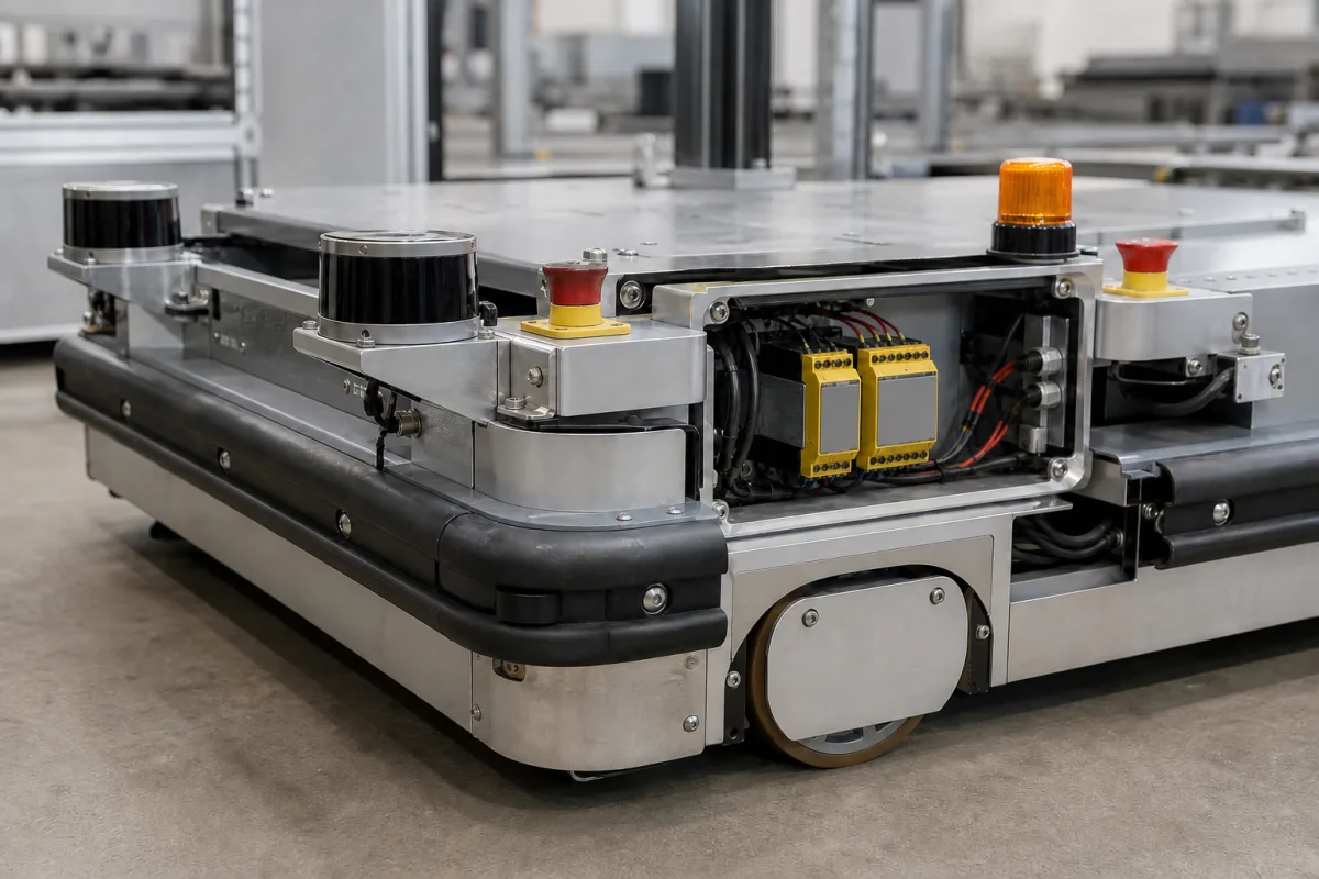
AGV on-board safety system (safety laser scanners, contact bumpers, emergency stops and safety relays that stop the vehicle before or on contact)
On-board personnel protection for AGVs · safety laser scanner protective and warning fields, scanner response time against travel speed, contact bumper overtravel and force limits, emergency stops and the safety relays that cut the drive
An AGV on-board safety system is the set of devices mounted on the vehicle itself that stop it before it reaches a person, or as soon as it touches one. A safety laser scanner on each corner or end watches a protective field in front of the direction of travel and switches its safety outputs when something enters; a soft contact bumper around the chassis trips a stop if anything is touched; emergency stop buttons on the sides let anyone halt the vehicle; and safety relays or a safety controller carry those signals to the drive amplifiers and brakes. The questions for a buyer are how far the vehicle travels after a detection, whether the scanner's fields and response time cover that distance at each speed, and how much force the bumper exerts before the vehicle stops.
Personnel and obstacle protection devices fitted to automated guided vehicles and carts: safety laser scanners and their field sets, contact bumpers and their evaluation units, emergency stop buttons, warning beacons and the safety relays or controllers that switch off the drive. This page treats the vehicle's whole stop chain, from detection to drive cut-off, rather than any one device: the scanner as a product, its type and field configuration, is covered on the Laser safety scanner page, and safety relay modules and emergency stop buttons have their own pages. Complete AGV systems with vehicles, guidance, traffic control and charging are covered on the Automated guided vehicle (AGV) system page, and reflector-based laser navigation scanners on the AGV laser navigation system page. Safety light curtains and scanners guarding fixed machines, press brake laser guards, and process plant safety instrumented systems are outside this page.
CNFX editorial research · Sources checked October 12, 2026 · 4 sources
Safety laser scanner fields against the distance the AGV travels after a detection
Hokuyo's UAM-05LP-T301, sold as a compact scanner for AGVs and AGCs, is certified to IEC 61496-1/3 Type 3, IEC 61508 SIL 2 and ISO 13849-1 PL d Category 3. It covers a 270° arc with a protective zone of up to 5 m and a non-safety warning zone of up to 20 m, scans every 30 ms at 2,000 rpm, stores up to 32 area patterns selected through 5 inputs on 2 channels, and lists an OSSD response time of 60 to 510 ms for switching off. [3]
The smallest object it detects grows with distance: 30 mm diameter up to 1.8 m, 50 mm up to 3.0 m and 70 mm up to 5.0 m. [3] The vertical test piece used in AGV standards, as described by NIST, is a cylinder 70 mm in diameter and 400 mm long representing the lower leg; the horizontal piece, 200 mm in diameter and 600 mm long, represents a person lying down. [1] Editorial note: on the Hokuyo figures, the 70 mm leg test piece falls within the detectable size out to the full 5 m protective range.
NIST's 2012 tests show why the field length matters. With the safety scanner wired straight into the drive amplifiers and only a stop field programmed, an obstacle in the field inhibited the amplifiers and the vehicle coasted up to 1.7 m from its full speed of 1 m/s, without extra braking. [1] NIST notes that a safety sensor is programmed with slow and stop fields, and that the standard's exception covers an object that appears inside the stopping distance, such as a pedestrian stepping into the path at the last instant. [1]
Editorial calculation: at 1 m/s the vehicle moves 60 mm during the scanner's shortest 60 ms response and 510 mm during the longest 510 ms setting, before any braking begins. Added to a 1.7 m coast-down, the stop field for that speed would need to reach beyond about 1.76 to 2.21 m, plus the scanner's +100 mm distance tolerance. [3][1] Switching to a shorter field at lower speed is what the stored area patterns are for.
Ask for the vehicle's stopping distance at each speed and load with the brakes the safety function actually uses, the scanner response time as configured, the field set for each speed and direction, the PL and category of the whole stop chain, and the probability of dangerous failure per hour of each device (Hokuyo lists PFHd 7.8×10⁻⁸ for one UAM unit).
02
Contact bumpers: actuating distance, overtravel and the force a bumper may exert
NIST's bumper test report quotes ANSI/ITSDF B56.5-2012: a bumper used as a force-sensing device shall be fail-safe in operation and mounting and shall not exert more than 134 N (30 lb) parallel to the floor against the direction of travel, and bumper activation shall cause a safety stop within the collapsible range of the bumper and before the vehicle strikes an obstacle. EN 1525 uses the same test pieces with limits of 750 N on the horizontal 200 mm piece and 250 N on the vertical 70 mm piece, and 400 N with the bumper compressed to the position reached in a stop from maximum speed and load. [2]
ASO's SENTIR safety contact bumper is a foam core over a sensor with two opposing contact elements on an aluminium profile, covered in artificial leather, and is certified to EN ISO 13856-3. Its manual gives actuating forces below 150 N with an 80 mm diameter test specimen and below 400 N with a 45 × 400 mm specimen, a 0 mm inactive edge, ±45° activation angle, more than 10,000 switching cycles, IP54 and 0 to +55 °C. [4]
The bumper height is chosen from the overtravel it must provide: ASO puts the actuating distance at 15% of bumper height, the overtravel distance at 60%, and the part that can no longer be compressed at 25%, as averages at a 10 mm/s test speed. [4] Editorial calculation: a 200 mm high bumper trips after about 30 mm and offers about 120 mm of overtravel; a vehicle at 0.5 m/s would need an average deceleration of at least 0.5² ÷ (2 × 0.12) ≈ 1.04 m/s² to stop within it, before allowing for relay and brake reaction time.
NIST illustrates four AGV bumper types — polycarbonate (Lexan), foam, supported foam and stainless steel — and found that a polycarbonate bumper with foam backing gave unreliable results in its tests because the foam interfered with the trigger switch. [2]
Ask for the bumper's actuating force, actuating distance and overtravel at your test piece sizes, the evaluation unit and its monitoring, and a stop test from maximum speed and load showing the vehicle halts inside the bumper's collapsible range.
03
From sensor to drive: safety outputs, bumper evaluation and the stop chain
Each device ends in a safety output that has to reach the drive. The Hokuyo scanner has two pairs of OSSD safety outputs, one for each of two protective zones it can monitor at once, plus non-safety warning outputs, external device monitoring and muting inputs. Up to four units can run master-slave with inputs and outputs wired to the master only, but actuators cannot be controlled over the master-slave bus. [3]
ASO's bumper uses a resistor-monitored circuit: up to five bumpers can be connected in series with a total length of no more than 25 m, one end on the evaluation unit and the other on an 8.2 kΩ terminating resistor. Contact bridges the resistor, and the evaluation unit signals the machine control through a potential-free relay contact, while cable breaks and tampering are monitored. [4]
ASO adds that the performance level of a bumper installation has to be determined for the whole machine from a risk assessment, and that its lab values do not release the machine builder from an application test. [4] NIST distinguishes controlled braking, an orderly slowing under continuous control, from the low-level emergency stop that the standard requires and that its test vehicle implemented by wiring the safety sensor into the drive amplifiers. [1]
Device
Published figure
What to confirm for your vehicle
Safety laser scanner
5 m protective, 20 m warning, 270°, 30 ms scan, 32 field patterns, OSSD off 60–510 ms [3]
Field set per speed and direction; configured response time
Scanner housing
80 × 80 × 95 mm, 0.8 kg, IP65, aluminium body with polycarbonate window, 24 V DC, 6 W without load [3]
Mounting height and position on each corner
Contact bumper
Actuating force <150 N (Ø80 mm) and <400 N (45 × 400 mm); overtravel 60% of height [4]
Height for the required overtravel; force at your test pieces
Bumper circuit
Up to 5 bumpers, 25 m total, 8.2 kΩ terminating resistor [4]
Evaluation unit and its PL
Force limits in standards
B56.5-2012: 134 N; EN 1525: 750 N / 250 N / 400 N [2]
Which standard the vehicle is built and tested to
04
Data for an AGV on-board safety system quotation
Paste it into your enquiry below or into an email to a maker, then replace every bracket.
Vehicle: [type; footprint; mass with maximum load; maximum speed forward, reverse and sideways]
Stopping: [stopping distance at each speed and load; brake type; controlled braking and emergency stop]
Scanners: [number and positions; protective and warning field lengths; number of field sets; required PL and category]
Bumpers: [height; overtravel; actuating force; test pieces and standard]
Emergency stops: [number and positions]
Warnings: [beacons; audible alarms]
Control: [safety relays or safety controller; interface to drive amplifiers; muting at docking stations]
Standards: [ANSI/ITSDF B56.5; EN 1525 or its successor; validation tests required]
Explore company information and manufacturing capabilities, then discuss the scope of your project with a relevant supplier.
Share this page
Compiled and source-reviewed by the CNFX editorial team.
Each manufacturer above links to the page on that company's own website where the product is listed, with the date we checked it. How we source and review
· Page last updated 13 October 2026
Buyer questions
How long is a safety scanner's protective field on an AGV?
It must cover the distance travelled during the scanner response time plus the vehicle's stopping distance at that speed; Hokuyo's UAM-05LP offers up to 5 m with 32 switchable patterns, and NIST measured a 1.7 m coast-down from 1 m/s on a stop-only test vehicle. [3][1]
What test pieces are used to check AGV obstacle detection?
A vertical cylinder 70 mm in diameter and 400 mm long representing a leg, and a horizontal cylinder 200 mm in diameter and 600 mm long representing a person lying down. [1]
How much force may an AGV bumper exert?
NIST quotes 134 N under ANSI/ITSDF B56.5-2012 for a bumper used as a force-sensing device, and 750 N, 250 N and 400 N limits under EN 1525 depending on the test piece and compression. [2]
How tall should a contact bumper be?
ASO sizes its SENTIR bumper so that overtravel, about 60% of the height, covers the stopping travel after contact; actuation takes about 15% of the height. [4]
Sources and what still needs a direct check
Sources checked 2026-10-12. NIST's Intelligent Systems Division tested AGV obstacle detection and bumper forces and quotes the ANSI/ITSDF B56.5 and EN 1525 requirements; Hokuyo and ASO are device makers stating their own specifications. The standards themselves govern the limits.