Safety sensing for stacker cranes and retrieval aisles
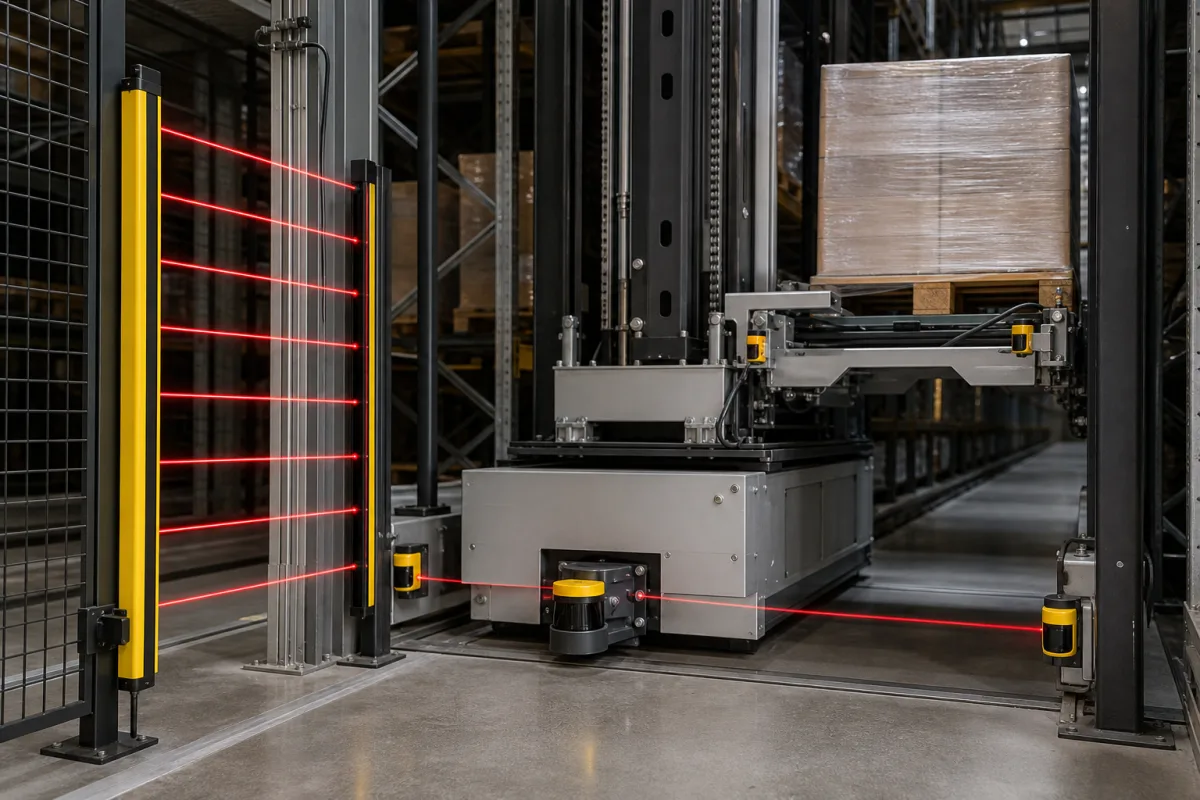
The illustration shows the entry to a storage aisle: a multi-beam light curtain on yellow columns at the aisle mouth, a retrieval vehicle with a safety laser scanner low on its front and small sensors on its load handler, carrying a pallet between racks. Each of those sensors serves a safety function with its own required performance level, and the function closest to people, entering the aisle, is handled as much by keys, doors and speed limits as by beams.
Covers safety sensing and safety functions on rail-dependent storage and retrieval machines (stacker cranes, transfer cars, satellite vehicles) and their aisles: EN 528 safety functions and performance levels, aisle access by key-dependent guarded doors with mode selection and escape release, safe-speed monitoring during maintenance, and the testing of camera person-detection systems on mobile machinery. Safety laser scanner field configuration is on Laser safety scanner; light curtain resolution and ISO 13855 safety distance are on Safety light curtains; safety relays and door interlock switches have their own pages; stacker crane ratings, aisle dimensions and throughput are on Pallet stacker crane for drum and chemical storage; environmental monitoring sensors are outside this page.
CNFX editorial research · Sources checked October 13, 2026 · 3 sources
ReeR's white paper on rail-dependent storage and retrieval equipment reproduces EN 528's table of safety-related parts with the required performance level (PL) for each.
For maintenance, fault clearance, inspection and setting, ReeR notes that EN 60204-32 requires hold-to-run controls for dangerous movements, reduced speed, an emergency stop at the control station and, where there is not enough room to escape, limited travel or a three-position enabling device.
ReeR lists the main hazards of storage and retrieval machines as shearing and crushing, falls from height at loading points and accesses, and injury during maintenance; accidents are infrequent but serious.
Safety function (EN 528 clause)
PL
Remark (ReeR)
Anti-derailment interlocking devices (5.5.4.2)
d
Only where derailing is not prevented purely mechanically
Load handling end stops (5.6.2)
b
Additional limiting devices
Limitation of forces (5.6.3)
b
Other limiting devices
Rotating devices, braking system (5.6.4)
c
Brake contactor
Satellite vehicle position monitoring (5.6.8.2)
b
Field devices; higher level via interlocks, sequence control and plausibility checks in the PLC
Hold-to-run devices in suspended safeguarding (5.7.6 a)
b
Field devices
Reduced speed in suspended safeguarding (5.7.6 b)
d (b)
b for field devices
Emergency stop at the control station (5.7.6 c)
c
—
Limited space to escape (5.7.6 d)
d (c)
c for the three-position enabling device, d for the control system
Sources disagree on the current EN 528 edition (ReeR cites EN ISO 528:2009). Ask the integrator which edition the machine is designed to and for the PL verification of each function.
02
Getting into the aisle: keys, doors and modes
ReeR and Fortress Interlocks both describe aisle access as a key-controlled sequence rather than a sensor that simply stops the machine.
ReeR's sequence: switch the machine from automatic to manual on an external key selector, whose key can only be removed in manual; the monitored door opens only with that key removed; inside, a second key selector must also be in manual before any movement, started by an internal start button and controlled with devices such as a three-position enabling switch. To return to automatic, the inside selector goes back to automatic and its key can only then be removed; the machine restarts only with the door closed and the external selector in automatic, from the external start button.
Fortress describes an EN 528 installation at a car maker's engine store: a self-closing guard with a networked interlock and key-operated mode switch, a padlockable dustcover so each person entering can lock it open, an internal key switch for manual crane operation, and an escape release for anyone trapped inside.
Door closed, both selectors in automatic, external start
The light curtain at the aisle mouth in the illustration detects passage; neither source relies on it alone for personnel access. Ask how the curtain, door interlock and key system are combined in the safety logic and at what PL.
03
Monitoring a safe speed during maintenance
EN 528 requires reduced speed when safeguarding is suspended but, as ReeR notes, does not state what speed is safe. ReeR assumes 2 m per minute for maintenance work on stacker cranes, low enough to avoid material falling from height and slipping under emergency braking, and monitors it with its SV MR0 safe speed monitor and two proximity switches for dual-channel sensing, reaching PL d.
2 m/min is about 33 mm/s (Editorial calculation), slow enough for a person beside the machine to follow its movement.
Item (ReeR example)
Value
Assumed safe maintenance speed
2 m/min (≈33 mm/s)
Sensing
2 proximity switches on the drive, dual channel
Monitor
SV MR0 safe speed module
Achieved
PL d
The 2 m/min figure is ReeR's assumption, not a standard value; the walking-pace remark is editorial. Ask the integrator which reduced speed is set, how it is monitored and what happens on overspeed.
04
How camera person-detection systems are tested
Where a mobile machine relies on a camera system that tells people from objects, DGUV Test's principles GS-BAU-71 (02.2026, written for earth-moving machinery) show what a test looks like.
A person detection system is defined as visual object recognition that distinguishes persons from objects by shape. The obstacle test object is a cylinder 40 to 50 cm in diameter and 80 to 100 cm high; test persons are 1.50 to 1.90 m tall in everyday clothing. Detection time must not exceed 300 ms. The obstacle is placed in at least 10 positions, with and without a high-visibility vest, and must never be reported as a person; the test person stands in at least 20 positions, with and without vest and helmet, at the near and far limits and in different orientations to the sensor. Lighting during the test is 50 to 80,000 lx.
Test element (GS-BAU-71)
Requirement
Obstacle object
Cylinder Ø 40–50 cm, 80–100 cm high; ≥10 positions; never detected as a person
Test person
1.50–1.90 m; ≥20 positions; with and without vest and helmet
Detection time
≤300 ms
Lighting
50–80,000 lx
GS-BAU-71 applies to earth-moving machinery and only the German version is binding; it is shown here as an example of how person detection is proven. Ask the retrieval-equipment supplier which standard its personnel detection was tested to.
05
What to ask a storage and retrieval machine supplier about safety sensing
Paste it into your enquiry below or into an email to a maker, then replace every bracket.
Ask for the list of safety functions with EN 528 clause, required and achieved PL, the sensors used for each, the aisle access sequence with keys, interlocks and escape release, how the aisle-entry light curtain or scanner fits the logic, the reduced speed in maintenance and how it is monitored, and test reports for any personnel detection system.
Explore company information and manufacturing capabilities, then discuss the scope of your project with a relevant supplier.
Share this page
Compiled and source-reviewed by the CNFX editorial team.
Each manufacturer above links to the page on that company's own website where the product is listed, with the date we checked it. How we source and review
· Page last updated 13 October 2026
Buyer questions
What performance level does EN 528 require for anti-derailment devices?
PL d where derailing is not prevented purely mechanically, according to the table ReeR reproduces. [1]
How is personnel access to a storage aisle controlled?
By key-dependent mode selection outside and inside the aisle, a monitored door that opens only with the key removed, and an escape release (ReeR; Fortress). [1][2]
What speed is safe for maintenance on a stacker crane?
EN 528 does not specify one; ReeR assumes 2 m/min and monitors it to PL d with a safe speed module and two proximity switches. [1]
How quickly must a camera person-detection system react?
DGUV Test's GS-BAU-71 sets a maximum detection time of 300 ms for mobile machinery. [3]
Sources and what still needs a direct check
Sources checked 2026-10-13. A safety-device maker's white paper, an interlock maker's application example and a German testing body's test principles.