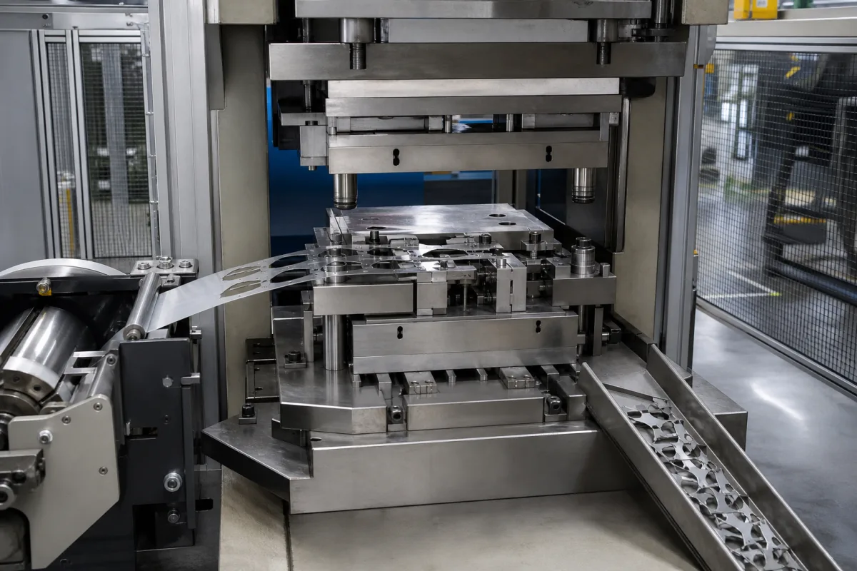
High-speed stamping module for small parts: a 200 kN compact press, servo strip feed and progressive die working as one station
The compact press, strip feed and progressive die that stamp small parts as one station of an automated line · 200 kN at up to 2,300 strokes per minute in a 600–700 mm tool opening, roll feeds rated ±0.05 mm at 120 m/min, and the pitch that leaves at full stroke rate
A stamping module is the smallest complete stamping unit: a press with its strip feed and a progressive die, set into a line where strip comes in and parts or a carrier strip go out. For connector contacts, lead frames or motor laminations the press runs at hundreds to thousands of strokes a minute, so the press, the feed and the die are specified together around the stroke rate and the strip pitch.
High-speed stamping modules for small parts: a compact automatic stamping press with its strip feed, progressive die and part or carrier-strip exit, working as one station in an automated production line. Coil-fed press lines, transfer, tandem and blanking lines with their decoilers, straighteners, die change and stacking are covered on the Automated stamping lines page; hot forging lines on the Automated hot forging line page. Servo roll feeders on their own, their feed window and pilot-release timing, are covered on the Servo feeder for press coil feeding page; progressive die design on the Progressive die set page; terminal reels and carrier-strip supply for insertion machines on the Vibratory bowl feeder and reel stand for terminal insertion page.
CNFX editorial research · Sources checked October 13, 2026 · 3 sources
200 kN at 100–2,300 strokes a minute: the force, stroke and tool space of a compact high-speed press
Bruderer's BSTA 200 is a 200 kN automatic stamping press with full mass balancing. Its data sheet lists three versions: the BSTA 200-60 and -70 with adjustable strokes of 8 to 38 mm (or a fixed stroke up to 44 mm) at 100–2,000 spm, and the BSTA 200HS-60 with strokes of 4 to 34 mm at 100–2,300 spm. [1]
The space for the die and the strip is what fixes which parts a module can make. The -60 versions have a 600 mm tool loading opening and a 590 × 426 mm bolster, the -70 a 700 mm opening and 690 × 426 mm bolster; the shut height is 181–236 mm (183–238 mm on the HS) with 40 mm of ram adjustment, and strip enters at 50–120 mm run-in height through an inlet up to 190 mm wide. Main motor power is 15 kW (18.5 kW on the HS), the press needs 6–10 bar compressed air, and weight is about 3,150–3,550 kg. [1]
BSTA 200 version
Stroke
Stroke rate
Tool loading opening
BSTA 200-60
8–38 mm adjustable; fixed up to 44 mm
100–2,000 spm
600 mm
BSTA 200-70
8–38 mm adjustable; fixed up to 44 mm
100–2,000 spm
700 mm
BSTA 200HS-60
4–34 mm adjustable
100–2,300 spm
600 mm
Give the die length and shut height, the stroke the die needs, and the stroke rate wanted; the press version follows from those three, not from force alone. [1]
02
Strip feed at stroke rate: ±0.05 mm at 120 m/min, 0.04 mm on a servo feeder, and the pitch left at 2,000 strokes
Schuler rates its Feedmax servo roll feed, developed for high-speed blanking lines and also fitted to universal and transfer presses, at coil speeds up to 120 m/min with a feed accuracy of ±0.05 mm, and its software works out the maximum feed performance for each die and stores it for later changeovers. [2] Tamco Engineering's SRF servo feeders state a feed accuracy of 0.04 mm from a servo resolver plus a measuring wheel on the strip, feed lengths of 1 to 9,999 mm, and an upper roll that can be opened every stroke, so that die pilots can register the strip, at 95–160 spm. [3]
Editorial calculation: at 120 m/min (120,000 mm/min) the average strip advance per stroke is 120,000 ÷ 2,000 = 60 mm at 2,000 spm, and 120,000 ÷ 2,300 ≈ 52 mm at 2,300 spm. A progressive die with a longer pitch would need a lower stroke rate or a faster feed; because the strip moves only during part of each stroke, the peak feed speed is higher than this average. [2][1]
The 95–160 spm figure for releasing the feed rolls on every stroke is far below the 2,000 spm of the press above, so at high stroke rates ask how the feed and the die pilots share registration of the strip. [3][1]
State strip width, thickness, material and pitch; ask for feed accuracy at your pitch and stroke rate, and how pilot release is handled.
03
What to send for a high-speed stamping module
Paste it into your enquiry below or into an email to a maker, then replace every bracket.
Part: [drawing; material; strip width and thickness]
Die: [progressive die length; shut height; stroke needed; pitch]
Rate: [parts per minute; strokes per minute]
Feed: [feed accuracy at pitch and rate; pilot release]
Line: [strip run-in height; exit as loose parts, carrier strip or stacked laminations]
Utilities: [power; compressed air; floor space and weight]
Explore company information and manufacturing capabilities, then discuss the scope of your project with a relevant supplier.
Share this page
Compiled and source-reviewed by the CNFX editorial team.
Each manufacturer above links to the page on that company's own website where the product is listed, with the date we checked it. How we source and review
· Page last updated 13 October 2026
Buyer questions
How fast can a compact stamping press run?
Bruderer lists its 200 kN BSTA 200 at 100–2,000 spm, and 100–2,300 spm for the 200HS-60 version. [1]
How accurate is a high-speed roll feed?
Schuler's Feedmax is rated at ±0.05 mm at coil speeds up to 120 m/min; Tamco's SRF servo feeder states 0.04 mm. [2][3]
What strip pitch can run at 2,000 strokes a minute?
Editorial calculation: at a 120 m/min coil speed the average advance is 60 mm per stroke at 2,000 spm, about 52 mm at 2,300 spm. [2][1]
Sources and what still needs a direct check
Sources checked 2026-10-13. Press data come from Bruderer's BSTA 200 technical data; roll feed speed and accuracy from Schuler's Feedmax page; servo feeder accuracy and pilot release from Tamco Engineering's SRF data sheet.