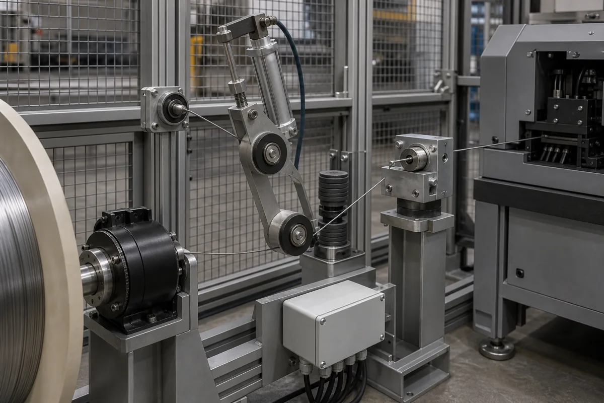
Wire pay-off tensioning system for spring coilers, wire benders and nail machines: dancer arm, turntable drive and brake
Wire pay-off with dancer arm · coil weight and wire size by pay-off model, motor-driven turntable or dancer-braked spool, 20–35° fleeting angle, wire-break stop
A wire pay-off tensioning system sits between the wire coil and a wire-processing machine such as a spring coiler, wire bender or nail machine. It carries the coil on a turntable, reel or spool shaft and uses a dancer or speed control arm, guide pulleys and either a drive motor or a brake to let wire off at the rate the machine draws it. Three choices decide the unit: the coil weight, dimensions and wire diameter it must take, whether the coil is driven by a motor that follows the arm or held back by a brake that the arm modulates, and how the wire path and wire-break stop are arranged.
Pay-off (de-coiler) units with dancer or speed control arms that feed wire from coils, reels or spools into spring coilers, wire forming and bending machines, nail machines and wire stranders. Tensioners that control enamelled copper or aluminium wire as it is wound into transformer and motor coils are covered on the Wire tensioner for coil winding page. Tension control for fabric on textile machines is covered on the Fabric tension control page, and for battery electrode foil on the Tension control system for lithium-ion battery electrode slitting page. Post-tensioning anchorages for prestressed concrete are outside this page.
CNFX editorial research · Sources checked October 12, 2026 · 4 sources
Driven turntable or dancer-braked spool: how the arm controls the wire
Enkotec's pay-off for its nail machines drives the turntable through a helical bevel geared motor, and a speed control arm read by a non-contact sensor sets the turntable speed; an electro-magnetic spring-loaded brake stops the turntable when the pay-off is switched off. [2] Here the arm commands the motor, so the coil is pushed out at the rate the machine draws wire.
Trimak's patented spool pay-off works the other way round. A dancer arm carrying two pulley wheels pivots about an axis parallel to the spool axis and takes up a position that depends on wire tension; levers turn that position into tension on a brake cable wrapped round a brake disc on the spool. When the wire tension rises above the set value the braking force falls, and when it drops below the set value the braking force rises. A spring, adjustable by hand, sets the reference tension. [4]
The same patent describes the result of tying the brake to the arm: the brake can be released to zero when tension rises at start-up, while full brake torque is applied during stops, so the spool does not keep turning and loosen the wire. It contrasts this with fixed brakes, where the pull needed to turn a full spool differs from the pull for a near-empty one. [4]
Editorial note: tell the supplier which arrangement the machine maker expects and whether the pay-off must stop with the machine's own stop signal.
Give the supplier the machine the pay-off feeds, the wire material and diameter range, the coil or spool form (strapped coil, coil on carrier, flanged spool), maximum coil weight and dimensions, the control arrangement (driven turntable with arm sensor, or dancer-modulated brake), the stop signal interface and the guarding to be supplied.
02
Coil weight, wire diameter and turntable speed across WAFIOS spring-coiler pay-offs
WAFIOS lists separate pay-off models for its spring coilers, and the wire range moves with the rating: the 150 kg AHT units take 0.1–1 mm or 0.12–0.8 mm wire, while the AHF 150 rated to 1,500 kg takes 2–5 mm wire. Each model is listed with the spring coilers it is matched to. [1]
Editorial calculation: on the AHT 1, a full coil at its 700 mm maximum outer diameter turning at 190 rpm lets off about π × 0.70 m × 190 ≈ 418 m of wire per minute; on the AHT 1HS, 760 mm at 330 1/min gives about 788 m/min. As the coil empties, the same rotational speed lets off less wire per minute, so the turntable speed has to follow the wire draw rather than stay fixed. [1]
Enkotec's pay-off for nail machines takes coils of up to 2,000 kg with up to 1,000 mm outside diameter and 380–620 mm inside diameter, and can be supplied with a stand for strapped coils without drums; because of its operating speed Enkotec recommends a fence round it. [2] SIMCO lists automatic pay-offs for spring machinery carrying 60 kg to 2,500 kg, for oil-tempered and standard steel wire. [3]
Dancer pulleys, fleeting angle and wire-break detection on the wire path
Trimak's patent puts the fleeting angle, the angle at which wire enters an exit eyelet, at 20° to 35° depending on the wire, and explains that pulling wire off near a spool flange at an angle drags it over the layer below and chafes it. Its dancer's receiving pulley traverses the spool width so the wire leaves at about 90° to the spool axis, and the fixed second pulley releases it along the cradle axis. [4]
The patent states that guiding the wire on rollers to the exit point removes the fleeting angle there and reduces friction by about one-half, which allowed finer, more break-prone wire to be run. [4] SIMCO's dancing-arm pay-offs add wire-break detection, a working timer and a feeding pulley block on the wire path to the spring machine. [3]
Editorial note: on a spring coiler or wire bender the last guide before the machine's straightener sets where the wire enters; ask for pulley groove size and material to suit the wire diameter range, and for a wire-break or slack-wire signal wired to stop the machine.
04
Coil, wire and control details for a pay-off quotation
Paste it into your enquiry below or into an email to a maker, then replace every bracket.
Machine fed: [spring coiler, wire bender, nail machine, strander; make and model]
Wire: [material; diameter range; oil-tempered or other]
Coil: [strapped coil, carrier, spool; max weight; inside and outside diameter; height]
Control: [driven turntable with arm sensor or dancer-modulated brake; reference tension adjustment]
Stops: [wire-break detection; stop signal from machine; brake on power-off]
Safety: [fence or guarding; power supply]
Explore company information and manufacturing capabilities, then discuss the scope of your project with a relevant supplier.
Share this page
Compiled and source-reviewed by the CNFX editorial team.
Each manufacturer above links to the page on that company's own website where the product is listed, with the date we checked it. How we source and review
· Page last updated 13 October 2026
Buyer questions
What size coil can a spring-coiler pay-off take?
WAFIOS lists 0–150 kg units for 0.1–1 mm wire up to 0–1,500 kg units for 2–5 mm wire, and heavier pay-offs rated to 3,000 kg. [1]
How does a dancer arm control the brake on a wire pay-off?
In Trimak's patent the arm's position, set by wire tension, is linked by levers to a brake cable on the spool's brake disc: higher tension reduces braking, lower tension increases it. [4]
How is a motor-driven wire pay-off controlled?
Enkotec drives the turntable through a geared motor whose speed is set by a speed control arm read by a non-contact sensor, with a spring-loaded brake for stopping. [2]
What is the fleeting angle on a wire pay-off?
The angle at which wire enters the exit eyelet; Trimak's patent puts it at 20° to 35° depending on the wire. [4]
Sources and what still needs a direct check
Sources checked 2026-10-12. WAFIOS and Enkotec are machine builders describing their own pay-off units; SIMCO's description is from its exhibitor listing on Expometals; the Trimak patent shows a dancer-to-brake mechanism rather than a current product.