Editorial Technical Reference

Top and Bottom Nozzles

This page explains how Top and Bottom Nozzles is classified within Machinery and Equipment Manufacturing. Technical values and manufacturer relationships are research references; confirm the current specification and supplier evidence for each order.

Technical Definition & Core Assembly

Structural components at the ends of a nuclear fuel assembly that provide flow distribution and structural support.
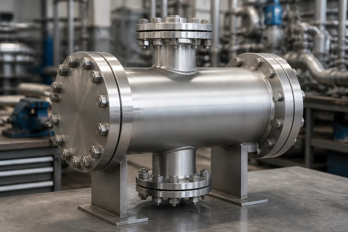
Representative product image. Confirm appearance and specifications with the manufacturer.

Product Specifications

Technical details and manufacturing context for Top and Bottom Nozzles

Definition
Top and bottom nozzles are critical components of nuclear fuel assemblies that serve as the inlet and outlet structures for coolant flow. The top nozzle directs coolant flow into the assembly while providing structural support and alignment. The bottom nozzle distributes coolant flow across the fuel rods and supports the assembly's weight within the reactor core. Both nozzles are designed to withstand high temperatures, pressure differentials, and radiation exposure while maintaining precise flow characteristics. They are typically fabricated from zirconium alloy, stainless steel, or Inconel, depending on the specific reactor design and operational requirements. The nozzles incorporate orifice patterns and flow channels to ensure uniform coolant distribution, preventing hot spots and maintaining thermal-hydraulic stability. Key parameters include overall length (200–400 mm), width (200–300 mm), height (100–200 mm), and weight (10–30 kg per nozzle). Material grades such as 304L–316L stainless steel are referenced per ASTM A240. Operating pressure ranges from 15–16 MPa, and temperature from 280–330°C. Flow rate per assembly is 5000–8000 m³/h, with a pressure drop of 0.1–0.3 MPa. Dimensional tolerance is ±0.1 mm per ISO 2768-m, and surface roughness is 0.8–3.2 µm Ra per ISO 4287. Neutron absorption cross-section is 0.1–0.5 barn. These values are typical ranges and must be verified for the specific fuel assembly design. The nozzles interface with guide tubes and other fuel assembly components, requiring precise fit and alignment. Verification questions include confirming material certifications, dimensional compliance, and pressure drop characteristics. Maintenance signals include wear, corrosion, or deformation that could affect flow distribution. Failure boundaries include loss of structural integrity or blockage of flow channels, which could compromise reactor safety.
Working Principle
The nozzles function as flow distributors and structural interfaces. Coolant enters through the bottom nozzle, flows upward through the fuel assembly to remove heat, and exits through the top nozzle. The nozzle designs incorporate specific orifice patterns and flow channels to ensure uniform coolant distribution across all fuel rods, preventing hot spots and maintaining thermal-hydraulic stability within the reactor core. The top nozzle also provides structural support and alignment for the assembly, while the bottom nozzle supports the assembly's weight. The materials and design must withstand high temperatures, pressure differentials, and radiation exposure.
Common Materials
Zirconium alloy, Stainless steel, Inconel
Technical Parameters
ParameterTypical rangeNotes & selection driver
Overall Length200–400 mmDepends on fuel assembly design
Overall Width200–300 mmSquare cross-section typical
Overall Height100–200 mmIncludes flow mixing vanes
Weight10–30 kgPer nozzle, depends on material and design
Material Grade304L–316LAustenitic stainless steel for corrosion resistanceASTM A240
Operating Pressure15–16 MPaTypical PWR primary circuit pressure
Operating Temperature280–330 °CReactor coolant temperature range
Flow Rate5000–8000 m³/hPer assembly, depends on core design
Pressure Drop0.1–0.3 MPaAcross nozzle, affects coolant flow
Dimensional Tolerance±0.1 mmCritical for fit with guide tubesISO 2768-m
Surface Roughness0.8–3.2 µmRa, affects pressure drop and corrosionISO 4287
Neutron Absorption Cross-Section0.1–0.5 barnLow absorption to minimize reactivity penalty

Ranges are indicative industry figures for RFQ preparation, not a supplier commitment. Confirm every value and standard with the legal manufacturer before ordering.

Components / BOM
  • Nozzle Plate
    Primary structural element containing flow orifices for coolant distribution
    Material: Zirconium alloy
  • Support Grid Part
    Provides structural support and alignment for fuel rods within the assembly
    Material: Zirconium alloy
  • Attachment Features Part
    Interface components for connecting to reactor internals and adjacent assemblies
    Material: Stainless steel
  • Flow Channels Part
    Designed passages that direct coolant flow through specific patterns
    Material: Zirconium alloy

Applied To / Applications

This component is essential for the following industrial systems and equipment:

Industrial Ecosystem & Supply Chain Structure

Complementary Systems
Downstream Applications
Specialized Tooling

Application Fit & Sizing Matrix

Operational Limits
pressure: 7-16 MPa (PWR), 7-8 MPa (BWR)
flow rate: 3-6 m/s coolant velocity
temperature: 250-350°C (typical PWR/BWR operating range)
slurry concentration: Not applicable (clean coolant only)
Media Compatibility
✓ Pressurized Water Reactor (PWR) coolant ✓ Boiling Water Reactor (BWR) coolant ✓ Zircaloy-4 fuel assembly structures
Unsuitable: High-velocity particulate slurry environments
Sizing Data Required
  • Fuel assembly length and grid spacing
  • Reactor coolant flow rate and pressure drop requirements
  • Neutronic and thermal-hydraulic design constraints

Reliability & Engineering Risk Analysis

Failure Mode & Root Cause
Abrasive erosion
Cause: High-velocity flow of particulate-laden fluids causing material loss, especially at nozzle throats and edges, leading to dimensional changes and reduced efficiency.
Cavitation
Cause: Rapid pressure drops below vapor pressure in the nozzle throat or downstream, forming vapor bubbles that implode violently, causing pitting and material fatigue.
Maintenance Indicators
  • Visible pitting, scoring, or material loss on internal surfaces, especially at the throat or exit.
  • Audible high-frequency whistling or hissing, indicating flow restriction or cavitation.
Engineering Tips
  • Implement regular ultrasonic thickness testing to monitor erosion rates and schedule replacements before failure.
  • Optimize flow conditions (e.g., reduce velocity, ensure proper backpressure) and use erosion-resistant coatings or materials like tungsten carbide.

Indicative industry ranges for design and RFQ preparation. Confirm the exact figures and applicable standard with the manufacturer before specifying.

Compliance & Manufacturing Standards

Applicable Standards
ASME B16.5 - Pipe Flanges and Flanged Fittings DIN EN 1092-1 - Flanges and their joints

Quoted from the published standard.

Manufacturing Precision
  • Bore Diameter: +/-0.05mm
  • Surface Flatness: 0.08mm per 100mm diameter
Quality Inspection
  • Dye Penetrant Test for surface defects
  • Dimensional Verification with Coordinate Measuring Machine (CMM)

Manufacturers of Top and Bottom Nozzles

Manufacturer profiles associated with Top and Bottom Nozzles.

Sourcing Top and Bottom Nozzles from China?
Tell us your specification and target quantity — we will match it against manufacturer records and come back with the factories that fit.
Request manufacturers We manufacture this

Manufacturer listings support early research and capability understanding. They are not certification, ranking, or transaction guarantees.

Technical documentation
Request current drawings, revision history, and a signed specification sheet.
Manufacturing capability
Verify equipment lists, process limits, capacity, and representative production evidence.
Inspection readiness
Confirm test methods, calibrated equipment, sampling plans, and traceable reports.
Supplier transparency
Check the legal entity, factory address, ownership, certifications, and direct contacts.

CNFX does not score or rank suppliers. Buyers must verify all claims and documents with the legal manufacturer before ordering.

Supply Chain Compatible Machinery & Devices

Heavy-Duty CNC Plasma Cutting Machine

The Heavy-Duty CNC Plasma Cutting Machine is a standalone industrial device designed for cutting conductive metals such as steel, stainless steel, aluminum, and copper alloys.

Explore Specs →
Automated Powder Coating System

Integrated industrial system for applying dry powder coatings to metal substrates.

Explore Specs →
Centrifugal Pump Impeller

The centrifugal pump impeller is a critical rotating component that converts mechanical energy from the motor into kinetic energy in fluid systems.

Explore Specs →
High-Precision CNC Laser Cutting Machine

Computer-controlled industrial machine using focused laser beams to cut sheet metal with micron-level accuracy.

Explore Specs →

Frequently Asked Questions

What are the typical materials used for top and bottom nozzles?

Typical materials include zirconium alloy, stainless steel, and Inconel. The specific material grade depends on the reactor design and operational requirements.

What is the function of the bottom nozzle?

The bottom nozzle distributes coolant flow across the fuel rods and supports the assembly's weight within the reactor core.

What are the key dimensions of these nozzles?

Typical overall length is 200–400 mm, width 200–300 mm, height 100–200 mm, and weight 10–30 kg per nozzle. These values vary with fuel assembly design.

How do I verify the specifications for a specific application?

You must confirm model-specific values, such as dimensions, material grades, and standards, with the legal manufacturer or supplier.

Data Basis

Editorial classification, named public sources where available, and source-reviewed manufacturer records.

Preliminary Technical Classification
This page supports structured research, RFQ preparation, and supplier evaluation. It does not replace buyer-led supplier qualification, standards review, or technical approval.
Buyer enquiry

Request manufacturing insight for Top and Bottom Nozzles

Ask for use case, specification boundaries, supplier type, and RFQ preparation information for this product.

Where it goes
Straight to the CNFX editorial desk, and to the manufacturer if this product is linked to a claimed profile. Nothing is broadcast to a supplier list.
Your details stay here
We do not sell or rent enquiry data, and we do not add you to a mailing list. Used only to answer this request.
No commission, no middleman
CNFX is a directory. We take no cut of any order and never negotiate on a supplier's behalf.
What we don't claim
A listing is not an endorsement. Qualify every supplier and verify every figure yourself before ordering.

Your business information is used only to process this request.

Thank you! Your message has been sent. We'll respond within 1–3 business days.
Sorry, we couldn't send your message. Please try again, or email us at contact@cnfx.com.

Need to Manufacture Top and Bottom Nozzles?

Compare manufacturer profiles with relevant product and process capability.

Previous Product
Z-axis Ram/Spindle
Last Product
Get QuotesChat