Editorial Technical Reference

Water Supply & Drain System

This page explains how Water Supply & Drain System is classified within Machinery and Equipment Manufacturing. Technical values and manufacturer relationships are research references; confirm the current specification and supplier evidence for each order.

Technical Definition & Core Assembly

Integrated system for delivering water to and removing wastewater from humidification equipment
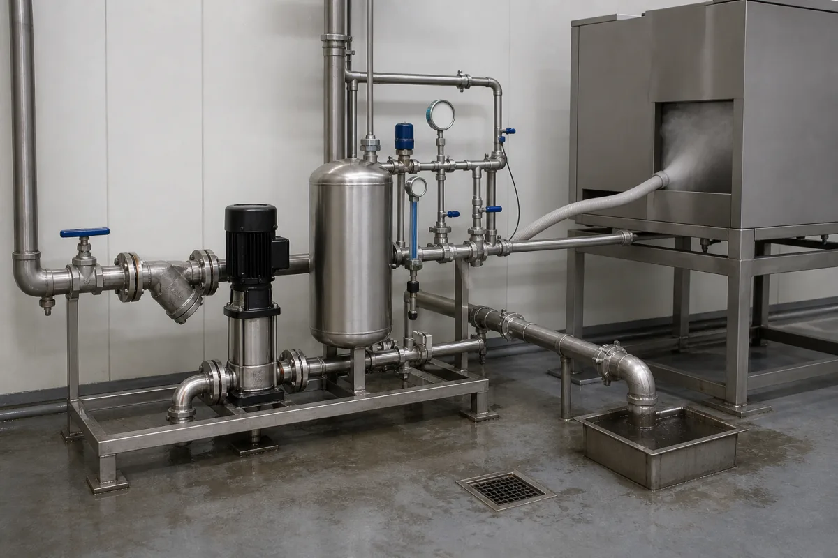
Water Supply & Drain System in a manufacturing environment
Representative product image. Confirm appearance and specifications with the manufacturer.

Product Specifications

Technical details and manufacturing context for Water Supply & Drain System

Definition
The Water Supply & Drain System is a component-level subsystem used in humidification equipment. It manages the complete water lifecycle: supplying treated water to the humidification unit, collecting excess moisture or condensate, and draining wastewater to maintain optimal operation and prevent water accumulation. The system typically includes pumps, valves, piping, and controls, and is designed to operate within specified parameters. Key parameters include a flow rate of 0.5–10 m³/h (per ISO 5167), operating pressure of 1.0–1.6 MPa, water temperature range of 5–40°C, ambient temperature range of -10–50°C, filtration rating of 50–200 μm (per ISO 16889), electrical supply of 24 V DC ±10%, power consumption of 10–50 W, ingress protection of IP54–IP65 (per IEC 60529), material grades 304/316L (per ASTM A240), connection sizes DN15–DN50 (per ISO 6708), and weight of 15–60 kg. Materials on file include stainless steel, PVC, and copper. These values are reference ranges; actual model-specific values must be confirmed with the legal manufacturer or supplier. The system is intended for integration into humidification systems, and its selection depends on humidification demand, piping compatibility, and environmental conditions. Verification of compliance with applicable standards and performance specifications is the responsibility of the purchaser. The system does not include the humidification unit itself, but interfaces with it via specified connections. Proper installation, operation, and maintenance are essential to avoid issues such as overflow, stagnation, or seal damage. The system is not a standalone product; it is a component designed for use within a larger humidification system.
Working Principle
The system uses pumps, valves, and piping networks to circulate water from a source to humidification components. Excess water or condensate is collected and removed via gravity drainage or pump-assisted systems. This maintains proper water levels and prevents overflow or stagnation. The system operates within specified pressure, temperature, and flow parameters, and includes filtration to protect nozzles. Electrical controls manage pump operation and valve actuation. The system is designed to operate within the specified ranges; deviations may lead to reduced performance or damage.
Common Materials
Stainless Steel, PVC, Copper
Technical Parameters
ParameterTypical rangeNotes & selection driver
Flow Rate0.5–10 m³/hSelect based on humidification demandISO 5167
Water Temperature Range5–40 °CAbove 40°C may damage seals
Ambient Temperature Range-10–50 °CBelow -10°C risk of freezing
Filtration Rating50–200 μmFiner filtration for nozzle protectionISO 16889
Electrical Supply24 ±10% V DCFor solenoid valves and controls
Power Consumption10–50 WDepends on pump and controls
Ingress ProtectionIP54–IP65IP65 for washdown areasIEC 60529
Material Grade304/316L316L for corrosive waterASTM A240
Connection SizeDN15–DN50Match to piping systemISO 6708
Weight15–60 kgSkid-mounted unit

Ranges are indicative industry figures for RFQ preparation, not a supplier commitment. Confirm every value and standard with the legal manufacturer before ordering.

Components / BOM
  • Supply Pump
    Delivers water from source to humidification units
    Material: Stainless Steel
  • Drain Valve
    Controls wastewater discharge from the system
    Material: Brass
  • Water Level Sensor
    Monitors and controls water levels to prevent overflow
    Material: Plastic/Stainless Steel
  • Distribution Piping Part
    Network of pipes for water transport throughout the system
    Material: PVC/Copper
  • Filtration Unit
    Strains the supply water so the humidifier nozzles do not scale up or block.
  • Electrical Controls
    Start and stop the pump and open and close the valves on demand.

Applied To / Applications

This component is essential for the following industrial systems and equipment:

Industrial Ecosystem & Supply Chain Structure

Complementary Systems
Downstream Applications
Specialized Tooling

Application Fit & Sizing Matrix

Operational Limits
pressure: 0.5 to 10 bar (operating), 15 bar (max burst)
flow rate: 0.5 to 50 L/min (per line)
temperature: 5°C to 60°C (operating), -10°C to 80°C (storage)
slurry concentration: ≤ 5% solids by weight (max for drain lines)
Media Compatibility
✓ Potable water ✓ Deionized water ✓ Non-corrosive humidifier condensate
Unsuitable: High-viscosity fluids or slurries with abrasive particles > 100 microns
Sizing Data Required
  • Required water supply flow rate (L/min)
  • Maximum system pressure (bar)
  • Drain line vertical lift height (meters)

Reliability & Engineering Risk Analysis

Failure Mode & Root Cause
Corrosion-induced leakage
Cause: Electrochemical degradation of metallic components (pipes, valves, fittings) due to water chemistry (pH, dissolved oxygen, chlorides) or galvanic reactions between dissimilar metals, leading to pitting, wall thinning, and eventual breach.
Mechanical blockage or reduced flow
Cause: Accumulation of mineral scale (e.g., calcium carbonate), biofilm, sediment, or foreign debris within pipes, pumps, or valves, often exacerbated by inadequate filtration, poor water treatment, or low flow velocities allowing settling.
Maintenance Indicators
  • Visible water stains, dampness, or pooling in areas around pipes, joints, or equipment, indicating active leaks.
  • Audible hammering or banging noises (water hammer) in pipes during valve closure or pump shutdown, signaling pressure surges that can damage components.
Engineering Tips
  • Implement a routine water quality monitoring and treatment program to control scaling, corrosion, and biological growth, adjusting chemical inhibitors (e.g., phosphates, biocides) based on periodic testing.
  • Install and maintain protective devices such as pressure-reducing valves, air vents, and expansion tanks to manage system pressure and prevent water hammer, and use corrosion-resistant materials (e.g., stainless steel, PVC) in critical or high-risk sections.

Indicative industry ranges for design and RFQ preparation. Confirm the exact figures and applicable standard with the manufacturer before specifying.

Compliance & Manufacturing Standards

Applicable Standards
ISO 15874:2013 (Plastics piping systems for hot and cold water installations) ANSI/NSF 61 (Drinking Water System Components - Health Effects) DIN EN 806-2 (Specifications for drinking water installations inside buildings)

Quoted from the published standard.

Manufacturing Precision
  • Pipe wall thickness: +/-0.1mm
  • Thread engagement depth: +/-0.5mm
Quality Inspection
  • Hydrostatic pressure test (1.5x working pressure for 1 hour)
  • Leak detection test with tracer gas or dye solution

Manufacturers of Water Supply & Drain System

Manufacturer profiles associated with Water Supply & Drain System.

Sourcing Water Supply & Drain System from China?
Tell us your specification and target quantity — we will match it against manufacturer records and come back with the factories that fit.
Request manufacturers We manufacture this

Manufacturer listings support early research and capability understanding. They are not certification, ranking, or transaction guarantees.

Share this page
Technical documentation
Request current drawings, revision history, and a signed specification sheet.
Manufacturing capability
Verify equipment lists, process limits, capacity, and representative production evidence.
Inspection readiness
Confirm test methods, calibrated equipment, sampling plans, and traceable reports.
Supplier transparency
Check the legal entity, factory address, ownership, certifications, and direct contacts.

CNFX does not score or rank suppliers. Buyers must verify all claims and documents with the legal manufacturer before ordering.

Supply Chain Compatible Machinery & Devices

Hydraulic Press

Industrial machine using hydraulic pressure to compress, form, or assemble materials

Explore Specs →
Heavy-Duty CNC Plasma Cutting Machine

The Heavy-Duty CNC Plasma Cutting Machine is a standalone industrial device designed for cutting conductive metals such as steel, stainless steel, aluminum, and copper alloys.

Explore Specs →
Automated Powder Coating System

Integrated industrial system for applying dry powder coatings to metal substrates.

Explore Specs →
Centrifugal Pump Impeller

The centrifugal pump impeller is a critical rotating component that converts mechanical energy from the motor into kinetic energy in fluid systems.

Explore Specs →

Frequently Asked Questions

What is the typical flow rate range for this system?

The reference flow rate range is 0.5–10 m³/h, based on ISO 5167. The actual required flow rate depends on the humidification demand of the specific application. Always confirm the model-specific value with the manufacturer.

What materials are commonly used in this system?

Materials on file include stainless steel, PVC, and copper. The material grade may be 304 or 316L, as per ASTM A240. The choice depends on water quality and environmental conditions. Verify material compatibility with the supplier.

What is the operating pressure range?

The reference operating pressure range is 1.0–1.6 MPa. Confirm the exact pressure rating for your model with the manufacturer.

What ingress protection rating does the system have?

The reference ingress protection range is IP54–IP65, per IEC 60529. IP65 is recommended for washdown areas. Verify the actual rating for your specific configuration with the supplier.

Data Basis

Editorial classification, named public sources where available, and source-reviewed manufacturer records.

Preliminary Technical Classification
This page supports structured research, RFQ preparation, and supplier evaluation. It does not replace buyer-led supplier qualification, standards review, or technical approval.
Buyer enquiry

Request manufacturing insight for Water Supply & Drain System

Ask for use case, specification boundaries, supplier type, and RFQ preparation information for this product.

Where it goes
Straight to the CNFX editorial desk, and to the manufacturer if this product is linked to a claimed profile. Nothing is broadcast to a supplier list.
Your details stay here
We do not sell or rent enquiry data, and we do not add you to a mailing list. Used only to answer this request.
No commission, no middleman
CNFX is a directory. We take no cut of any order and never negotiate on a supplier's behalf.
What we don't claim
A listing is not an endorsement. Qualify every supplier and verify every figure yourself before ordering.

Your business information is used only to process this request.

Thank you! Your message has been sent. We'll respond within 1–3 business days.
Sorry, we couldn't send your message. Please try again, or email us at [email protected].

Need to Manufacture Water Supply & Drain System?

Compare manufacturer profiles with relevant product and process capability.

Previous Product
Z-axis Ram/Spindle
Last Product
Get QuotesChat