Rotor balancing · Balance grade and permissible unbalance, two-plane split, correction by milling or drilling, automatic stations
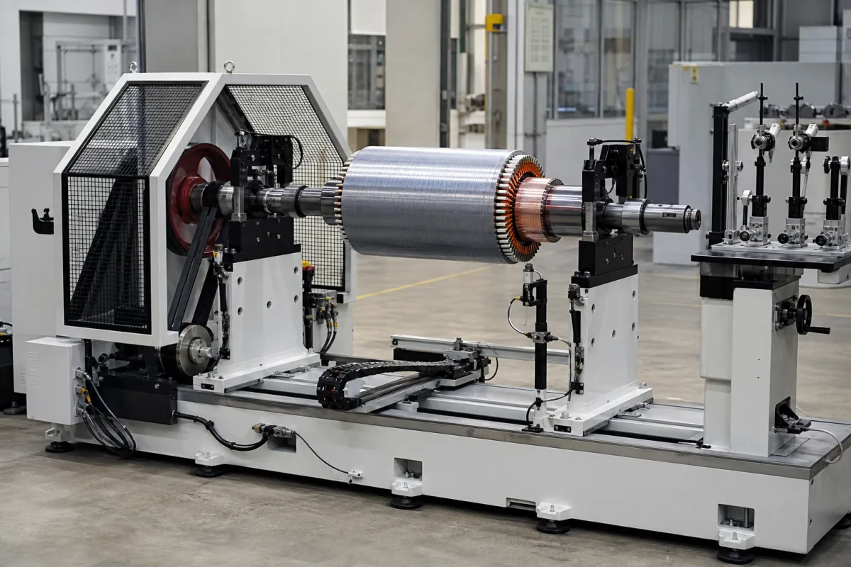
An electric motor rotor balancing machine spins a motor rotor or armature on its journals, measures the unbalance in one or two correction planes, and shows or makes the correction, either manually with weights or automatically by drilling or milling material away. Ask three things first: what residual unbalance tolerance your rotor must meet at its service speed, how the tolerance is split between the correction planes, and how the machine measures, corrects and re-checks the rotor at your production rate.
Horizontal balancing machines for motor rotors and armatures, from universal manual machines to automatic multi-station machines with drilling or milling correction. Field balancing instruments, flexible-rotor high-speed balancing and the rotors themselves are outside this page.
CNFX editorial research · Sources checked October 11, 2026 · 4 sources
Set the balance tolerance from grade, speed and mass
ISO 1940-1:2003 (BS ISO 1940-1), for rotors in a constant (rigid) state, specifies balance tolerances, the necessary number of correction planes and methods of verifying residual unbalance, and recommends balance quality requirements by machinery type and maximum service speed. It states acceptance criteria between the maker and user of rotating machines and does not cover flexible rotors. [1]
Sensemore, a vibration monitoring company, explains that ISO 21940-11 superseded ISO 1940-1 and that a balance quality grade is the permissible specific unbalance multiplied by the angular velocity at service speed, in mm/s; because speed is in the product, the permissible eccentricity halves each time the service speed doubles. For two correction planes roughly symmetric about the centre of gravity, half the permissible unbalance goes to each plane; otherwise the standard allocates and bounds the split. It notes that a machine builder's stated tolerance governs over the grade. [2]
Editorial calculation: assuming grade G 2.5 (take the real grade for your rotor from ISO 21940-11 or the motor's specification), a 5 kg rotor at 3,000 rpm turns at 314 rad/s, so permissible eccentricity is 2.5 × 1000 ÷ 314 ≈ 8.0 µm and permissible unbalance about 8.0 × 5 ≈ 40 g·mm, or about 20 g·mm per plane; at a 30 mm correction radius that is about 0.66 g per plane. [2]
Give the supplier the rotor drawings (mass, length, journal and bearing positions, diameters), service speed, required balance grade or tolerance, correction planes and radii, correction method (weights, drilling, milling), production rate, rotor variants and changeover, and data interfaces.
02
Plan correction and stations for your volume
Schenck's armature balancing page notes that rising electric motor speeds raise the demands on armature balancing quality, and offers four-, five- and six-station automatic machines that correct by milling or drilling adapted to rotor geometry. Its KBTU series corrects by profile, polar or slot milling or drilling in one or two planes, with a transfer station, measuring station, correction stations, a separate measuring station for an audit check, internal lifting and turning transport, control cabinet and protective device. [3]
Its five-station CIVO is described as suited to up to about 2 million small armatures a year, up to 500 g (optionally 3 kg). Interfaces for line control and MES data are offered. [3]
Editorial calculation: 2 million armatures a year over an assumed 6,000 production hours is about 333 per hour, or one every 11 s; use your own hours and volume to set the cycle time you ask suppliers to guarantee, including the audit re-measurement. [3]
03
Verify the machine's own unbalance before accepting readings
US patent 10,101,235 B2, granted to the individual applicant Weijian Guo, notes that balancing machines are evaluated under ISO 2953:1999 (Balancing machines — Description and evaluation) or the Chinese standard GB/T 4201-2006 using two terms, Minimum Achievable Residual Unbalance (Umar) and Unbalance Reduction Ratio (Urr). It argues that the unbalance a machine reports for a rotor is the vector sum of the machine's own unbalance and the rotor's, so two machines can disagree on the same rotor with no way to tell which is right. [4]
The patent's remedy is an index test: measure the rotor in two planes, turn it 180° relative to the drive while keeping the angle reference consistent, and measure again. The machine's contribution stays fixed in amount and angle while the rotor's keeps its amount and reverses direction, so the machine's unbalance is the midpoint of the two readings and the rotor's unbalance is the vector from that midpoint to each reading. Repeating at more angles improves accuracy, and correcting the rotor to zero and adding known weights in drilled holes yields a reference rotor of definite unbalance. [4]
Editorial calculation with assumed readings in one plane: if the machine reads 30 g·mm at 0° before indexing and 10 g·mm at 0° after the 180° turn, the machine's own unbalance is (30 + 10) ÷ 2 = 20 g·mm and the rotor's is (30 − 10) ÷ 2 = 10 g·mm. Against the 20 g·mm per plane tolerance worked out above for a G 2.5, 5 kg, 3,000 rpm rotor, the uncorrected reading of 30 g·mm would reject a rotor that is within tolerance. [4][2]
Editorial note: ask the supplier to show Umar and Urr test results at acceptance, which proving rotor they use, and whether the machine software supports an index (180°) compensation run for your fixtures and adaptors.
Check
What it shows
Source
Minimum Achievable Residual Unbalance (Umar)
Evaluation term in ISO 2953:1999 and GB/T 4201-2006; the patent argues it has no clear physical meaning.
Fill the specification fields with values for your rotors
A balancing machine quotation needs values for your rotors. The table explains each field, gives published values where a reviewed source states them, and says what to obtain from the supplier.
Field
What it means and published values
Ask the supplier for
Maximum rotor weight (kg)
Up to 500 g (option 3 kg) on one automatic model. [3]
Weight range.
Balancing speed range (RPM)
Measuring speed.
Range.
Unbalance reduction ratio (%)
Share of initial unbalance removed per run.
Guaranteed ratio.
Rotor diameter range (mm)
Fits your rotors.
Range.
Measurement accuracy (g·mm/kg)
Must resolve the tolerance, e.g. ~8 g·mm/kg for G 2.5 at 3,000 rpm. [2]
Minimum achievable residual unbalance.
Power consumption (kW)
Utility.
Value.
Supply voltage (V AC)
Site supply.
Voltage.
Operating temperature (°C)
Shop ambient.
Range.
Relative humidity (%)
Shop ambient.
Range.
Ingress protection
Enclosure.
IP code.
Machine weight (kg)
Foundation.
Weight.
Footprint (L×W×H)
Layout.
Drawing.
07
Send the rotor, tolerance and volume data together
Paste it into your enquiry below or into an email to a maker, then replace every bracket.
Rotor: [mass; length; journals; diameters]
Tolerance: [grade or g·mm; service speed; planes]
Correction: [weights; drilling; milling; radii]
Volume: [rotors per year; cycle time; variants]
Checks: [audit re-measure; data to MES]
Supply: [voltage; air; floor space]
Explore company information and manufacturing capabilities, then discuss the scope of your project with a relevant supplier.
Share this page
Compiled and source-reviewed by the CNFX editorial team.
Published product pages show what a company offers, not tested performance. Confirm the legal seller, factory and scope for your order. How we source and review
· Page last updated 13 October 2026
Buyer questions
What does balance grade G 2.5 mean?
The grade is permissible eccentricity times angular velocity in mm/s; at 3,000 rpm G 2.5 allows about 8 µm, or 8 g·mm per kg of rotor. [2]
How is the tolerance split between two planes?
For planes roughly symmetric about the centre of gravity, half to each plane; otherwise the standard allocates and bounds the split. [2]
How do automatic machines correct armature unbalance?
Schenck's machines mill or drill material in one or two planes and re-measure at an audit station. [3]
Why do two balancing machines give different readings for the same rotor?
US patent 10,101,235 B2 explains that each reading is the vector sum of the machine's own unbalance and the rotor's; indexing the rotor 180° and measuring again lets you separate the two. [4]
Sources and what still needs a direct check
Sources checked 2026-10-11. BSI summarises ISO 1940-1 (since superseded by ISO 21940-11), whose grade table was not read for this page; Sensemore explains the grade arithmetic; Schenck describes its own armature balancers; US patent 10,101,235 B2 describes how machine and rotor unbalance are separated.