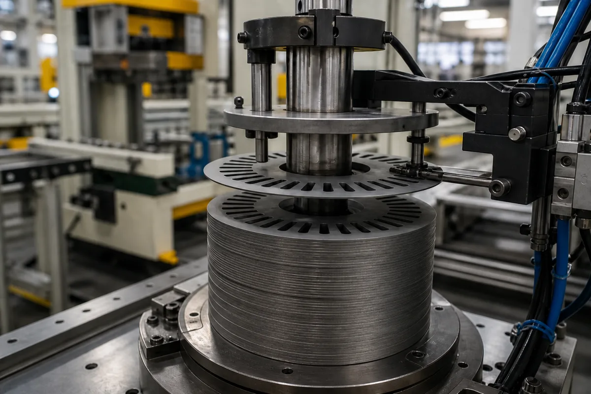
Rotational and skew stacking mechanism for rotor cores: indexing each lamination for slot skew and turning the stack to cancel strip thickness variation
The rotating part of a rotor-core stacker · indexing each lamination by a fraction of a degree to build skewed slots, turning the stack by 180° or another set angle to cancel wedge-shaped strip, and keeping both right when the sheet thickness drifts
A rotor core for an induction or permanent-magnet motor is a stack of thin laminations, and two things about it are set by how each lamination is turned as it joins the stack. The first is skew: the slots or magnet pockets are twisted along the core to reduce cogging, which is done by rotating each lamination a small fixed step relative to the one below. The second is squareness: electrical-steel strip is never exactly the same thickness from edge to edge, so a stack of identically oriented laminations grows into a wedge, and turning laminations by 180° or another large angle spreads the thick edge around the core. The stacking mechanism that does both is a servo-driven rotating die barrel or lamination holder, placed at the stacking station of a progressive die in the LH Carbide and Mitsui designs below, and controlled from a strip thickness measurement and a stack-height count.
Rotating stacking mechanisms for rotor and stator lamination cores: servo-indexed choke barrels and lamination holders in progressive dies and off-line stackers that build slot skew step by step, turn laminations by 180° or other compensating angles against strip thickness variation, and adjust the skew step from measured sheet thickness and stack height, together with the interlock and caulking geometry that limits the rotation angles. Stack-and-weld machines are covered on the Electric motor rotor lamination stacking and welding machine page; pick-and-place stacking heads over guide rods on the Precision stacking head for stator laminations page; pressing fixtures for bonded stacks on the Stacking and bonding fixture for self-bonding electrical-steel laminations page; finished stacks on the Electric motor stator lamination stack page. The stamping press itself is outside this page.
CNFX editorial research · Sources checked October 13, 2026 · 4 sources
Skew built step by step at 0.1–0.2° per lamination, and recalculated as Δθ = θ₀/n when the sheet thickness drifts
Mitsui High-Tec's US patent 4,597,168 describes the problem with a fixed skew step and the control loop that replaces it.
The patent explains that a conventional die rotates the stack by a constant skew angle each time a sheet lands, for example 0.1°–0.2°, so the total skew is that angle times the number of sheets; when cores are cut to a fixed height rather than a fixed count, any change in sheet thickness changes the count and therefore the skew of the product. [1] Its method takes the desired core thickness L₀, the measured sheet thickness and the total skew θ₀, counts sheets and measures stack height as each core is built, and when the height reaches L₀ computes a new step Δθ = θ₀/n from the actual sheet count n, which a servomotor and reduction gear apply to the next core. [1]
For 0.5 mm sheet, the patent notes that the finished core can come out up to 0.5 mm thicker than L₀, and that setting the reference to L₀ − 0.25 mm holds the deviation to about ±0.25 mm. [1]
Editorial calculation: assume a 60 mm core with 18° of total skew. At 0.50 mm sheet that is 120 laminations at 0.15° each (18 ÷ 120). If the strip runs at 0.49 mm, the same height takes about 122 laminations (60 ÷ 0.49); a fixed 0.15° step would then give about 18.4°, while Mitsui's recalculated step would be about 0.148° (18 ÷ 122). The figures are illustrative assumptions; the method is the patent's. [1]
Give the core height, the total skew angle and direction, the nominal lamination thickness and its tolerance, and whether cores are cut by count or by height.
02
Turning the stack against wedge-shaped strip: 180° reversals from an edge-to-edge thickness gauge, or turns of 360° divided by the number of interlock tabs
Two US patents describe the compensating turns and what limits them.
Greenway also contemplates skew steps of less than 1° between adjacent laminas alongside the large compensating turns, and notes that the turns must add up to 360° so the laminas below a group of truing laminas return to their original orientation, apart from the skew. [4] LH Carbide's operator enters the stack height, skew angle, skew direction and nominal lamina thickness, and the controller derives the indexing from them. [3]
The picture above shows the end of such a process: slotted rotor laminations stacked on a vertical arbor over a turntable, with a top plate, guide pins and a sensing arm reaching in from the side.
Item
LH Carbide (US 5,359,763)
Greenway (US 5,649,349)
Measurement
Thickness gauge on the incoming strip: carbide rollers above and below, with sensors reading both edges and the edge-to-edge differential [3]
Not the subject; compensation applied as a fixed pattern [4]
Turn applied
Choke ring die barrel indexed by the skew increment plus an extra 180° when the differential is excessive; number of reversals operator-entered or set automatically [3]
Every other lamina turned 180°, or groups of truing laminas turned 180°, 90° or 45°; earlier art (Bruhn) turned laminas by a large increment, such as 90° [4]
Drive
Servomotor gear drive; actual barrel position compared with the commanded one and the error drives the motor [3]
Compensating turns summing to a multiple of 360° so the standard laminas keep their skew orientation [4]
Interlock limit
—
With interlock tabs, compensating turns must be multiples of 360° divided by the number of tabs; four tabs give 90° steps [4]
State the number and position of interlock tabs or the joining method, the strip thickness tolerance edge to edge, and the squareness required of the finished core.
03
Skew left adjustable after stacking: caulking holes made longer than their projections
Mitsui High-Tec's European application EP 1 617 542 points out that once laminations are caulked together with the skew built in, the skew can no longer be changed if the motor's use changes. [2] Its core puts caulking projections and holes on the same radius from the rotation centre but makes each hole longer in the circumferential direction than the projection that fits it, so a gap remains and the laminations can be turned relative to each other after caulking to set the skew. [2] In one embodiment wide holes sit at 0° and 240° and narrow holes at 60° and 300° on one piece, with the next pieces using 0°, 120°, 180° and 240° positions, so holes and projections pass through two or more layers. [2]
For a stacking mechanism this changes the job: it stacks and caulks without the final skew, and a later operation twists the core, so the barrel's indexing accuracy matters less than the hole-to-projection clearance designed into the lamination.
Say whether the skew must be fixed in the die or set later, and supply the lamination drawing with caulking or interlock positions.
04
Rotational stacking mechanism data to send
Paste it into your enquiry below or into an email to a maker, then replace every bracket.
Lamination: [outer and inner diameter; slot count; thickness and tolerance]
Core: [height; cut by count or height; squareness]
Skew: [total angle; direction; straight, continuous or stepped]
Compensating turns: [180°; 360°/tabs; pattern]
Joining: [interlock tabs and positions; caulking; bonding]
Measurement: [strip thickness gauge; stack height]
Press and die: [strokes per minute; station available]
Explore company information and manufacturing capabilities, then discuss the scope of your project with a relevant supplier.
Share this page
Compiled and source-reviewed by the CNFX editorial team.
Each manufacturer above links to the page on that company's own website where the product is listed, with the date we checked it. How we source and review
· Page last updated 13 October 2026
Buyer questions
How is rotor slot skew made in a progressive die?
The die rotates the stack by a small step each time a lamination lands; Mitsui High-Tec cites 0.1°–0.2° per sheet, with the total skew equal to the step times the number of sheets. [1]
Why turn laminations by 180°?
To cancel strip that is thicker on one edge: LH Carbide's die gauges both edges and adds 180° reversals of the choke barrel when the differential is excessive. [3]
What limits the compensating rotation angle?
Interlock tabs: Greenway's patent requires turns in multiples of 360° divided by the number of tabs, so four tabs give 90° steps. [4]
Can skew be changed after the core is stacked?
Mitsui High-Tec's EP 1 617 542 makes caulking holes longer than their projections so the laminations can still be turned after caulking. [2]
Sources and what still needs a direct check
Sources checked 2026-10-13. Four patents from three applicants: Mitsui High-Tec's US 4,597,168 on recalculating the skew step and its EP 1 617 542 on skew set after caulking, LH Carbide's US 5,359,763 on a rotating choke barrel with strip thickness gauging, and Glenn Greenway's US 5,649,349 on compensating rotations.