Editorial Technical Reference

Automated Multi-Stage Lens Assembly and Testing System

This page explains how Automated Multi-Stage Lens Assembly and Testing System is classified within Manufacture of Optical Instruments and Photographic Equipment. Technical values and manufacturer relationships are research references; confirm the current specification and supplier evidence for each order.

Technical Definition & Core Assembly

Integrated production line for assembling and testing complex optical lens systems
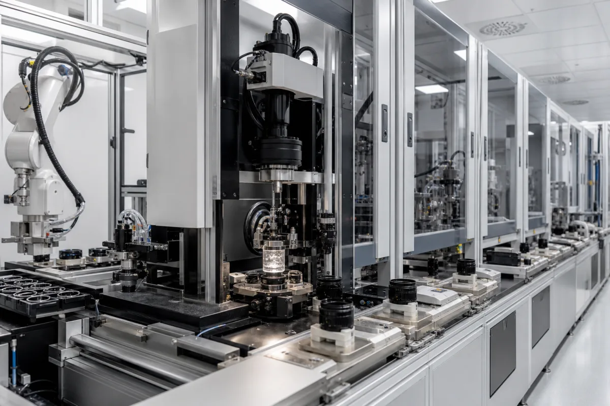
Representative product image. Confirm appearance and specifications with the manufacturer.

Product Specifications

Technical details and manufacturing context for Automated Multi-Stage Lens Assembly and Testing System

Definition
The Automated Multi-Stage Lens Assembly and Testing System is a fully automated industrial production system designed for high-volume assembly and quality verification of multi-element optical lens systems. This integrated line coordinates multiple specialized modules, including precision handling, optical alignment, bonding, and metrology stations, to ensure consistent production of camera lenses, microscope objectives, and other optical instruments requiring precise component stacking. The system minimizes human intervention while maintaining micron-level accuracy throughout the assembly process. It is suitable for manufacturers of optical instruments and photographic equipment seeking to automate their lens assembly and testing operations. The system handles lens elements up to 100 mm in diameter and as thin as 0.5 mm, with an alignment accuracy of ±0.5 μm and a positioning resolution of 0.1 μm. Throughput ranges from 120 to 240 assemblies per hour, with a cycle time of 15 to 30 seconds per assembly. The system operates under cleanroom conditions (ISO 14644-1 class 20±2) and requires a footprint of 8×3 m². It uses clean dry air at 0.6–0.8 MPa (ISO 8573-1) and a three-phase 380 V AC power supply (IEC 60038). The system weighs approximately 4500 kg and includes all modules and frame. It performs optical testing in the visible spectrum (400–700 nm) for MTF and interferometry, with a data acquisition rate of 1000 Hz for real-time quality monitoring. The system is constructed with a stainless steel frame, aluminum alloy mounting plates, precision linear guides, and optical grade glass handling components. For procurement, verify model-specific values and standards with the legal manufacturer or supplier.
Working Principle
The system uses robotic arms and precision stages to transport lens elements between modular workstations. At each station, automated alignment, adhesive application, curing, and optical testing occur in sequence under controlled environmental conditions. The process begins with feeding individual lens elements, which are then precisely positioned using high-resolution stages. Alignment sensors ensure micron-level accuracy before bonding. After curing, the assembled lens undergoes optical testing, including MTF and interferometry, to verify performance. Data acquisition at 1000 Hz enables real-time quality monitoring and feedback for process adjustment.
Common Materials
Stainless Steel Frame, Aluminum Alloy Mounting Plates, Precision Linear Guides, Optical Grade Glass Handling Components
Technical Parameters
ParameterTypical rangeNotes & selection driver
Alignment AccuracyRequired±0.5 μmPrecision of optical axis alignment between elements
Throughput RateRequired120–240 assemblies/hourMaximum completed assemblies per hour
Maximum Lens DiameterRequired100 mmLargest optical element the system can process
Minimum Element ThicknessRequired0.5 mmThinnest lens element that can be reliably handled
Environmental Control20±2 classCleanroom classification maintained during assemblyISO 14644-1
System FootprintRequired8×3 Total floor space required for installation
Operating Pressure0.6–0.8 MPaClean dry air for pneumatic actuatorsISO 8573-1
Power Supply380±10% V ACThree-phase, 50/60 HzIEC 60038
Cycle Time15–30 sPer lens assembly and test
Positioning Resolution0.1 µmFor precision placement of elements
Testing Wavelength Range400–700 nmVisible spectrum for MTF and interferometry
Data Acquisition Rate1000 HzFor real-time quality monitoring
Weight4500 kgIncludes all modules and frame

Ranges are indicative industry figures for RFQ preparation, not a supplier commitment. Confirm every value and standard with the legal manufacturer before ordering.

Components / BOM
  • Precision Robotic Handling Module
    Transports lens elements between stations with micron-level positioning
    Material: Aluminum alloy with ceramic bearings
  • Active Optical Alignment Station
    Automatically aligns optical elements using interferometric measurement
    Material: Granite base with stainless steel mounts
  • UV Curing Chamber
    Cures optical adhesives with controlled UV exposure
    Material: Stainless steel housing with quartz windows
  • Automated Metrology Module
    Performs final optical testing including MTF and wavefront analysis
    Material: Vibration-isolated aluminum platform
  • Environmental Control Enclosure Optional
    Maintains temperature, humidity, and particulate control
    Material: Polycarbonate panels with HEPA filtration
  • Lens Element Feeder
    Presents individual lens elements to the handling robot at the head of the line.
  • Adhesive Application Unit
    Lays down the optical adhesive before the elements are aligned and cured.

Industry Taxonomies & Aliases

Commonly used trade names and technical identifiers for Automated Multi-Stage Lens Assembly and Testing System.

Industrial Ecosystem & Supply Chain Structure

Complementary Systems
Downstream Applications
Specialized Tooling

Application Fit & Sizing Matrix

Operational Limits
pressure: Atmospheric to 1.5 bar (21.8 psi) clean dry air supply
other spec: Class 1000 cleanroom, 0.1-5% slurry concentration for polishing stages, 50-60 Hz power, <1 μm vibration isolation
temperature: 15-30°C (59-86°F) controlled environment
Media Compatibility
✓ Optical glass substrates ✓ Polymer optical elements ✓ Ceramic lens housings
Unsuitable: Corrosive chemical environments or conductive metal particle contamination
Sizing Data Required
  • Maximum lens diameter (mm)
  • Annual production volume (units/year)
  • Number of optical elements per assembly

Reliability & Engineering Risk Analysis

Failure Mode & Root Cause
Misalignment-induced optical distortion
Cause: Gradual wear in precision linear guides and servo motor encoders, exacerbated by thermal expansion/contraction cycles and particulate contamination from the assembly environment, leading to cumulative positional errors in lens placement stages.
Contamination-induced surface defects
Cause: Inadequate cleanroom protocols or filter degradation in the environmental control system, allowing microscopic particles (dust, oils, fibers) to settle on lens surfaces during handling or testing, causing scratches, adhesion issues, or failed optical performance tests.
Maintenance Indicators
  • Audible: Unusual high-pitched whining or grinding noises from servo motors or linear actuators, indicating bearing wear, lubrication failure, or mechanical obstruction.
  • Visual: Increased rejection rate or inconsistent readings on automated interferometers or MTF (Modulation Transfer Function) testers, signaling optical misalignment, calibration drift, or sensor degradation.
Engineering Tips
  • Implement predictive maintenance via vibration analysis and thermal imaging on high-precision motion components (e.g., ball screws, linear guides) to detect early wear patterns, and use automated laser alignment tools for weekly verification of optical axis integrity.
  • Enhance contamination control with HEPA-filtered laminar flow enclosures for critical stages, establish strict particle count monitoring, and use antistatic materials for lens handling; regularly calibrate test instruments with NIST-traceable standards to maintain measurement accuracy.

Indicative industry ranges for design and RFQ preparation. Confirm the exact figures and applicable standard with the manufacturer before specifying.

Compliance & Manufacturing Standards

Applicable Standards
ISO 10110-7:2017 (Optics and photonics - Preparation of drawings for optical elements and systems - Surface imperfection tolerances) ANSI Z80.1-2020 (Ophthalmic Lenses - Prescription Requirements) DIN 3140-7:2018 (Optics and optical instruments - Preparation of drawings for optical elements and systems - Surface form tolerances)

Quoted from the published standard.

Manufacturing Precision
  • Centering tolerance: +/- 0.01 mm (for lens alignment in mounts)
  • Surface irregularity: λ/4 (at 632.8 nm wavelength for optical performance)
Quality Inspection
  • Interferometric surface testing (for optical quality and flatness verification)
  • Automated optical inspection (AOI) with image analysis for assembly verification and defect detection

Manufacturers of Automated Multi-Stage Lens Assembly and Testing System

Manufacturer profiles associated with Automated Multi-Stage Lens Assembly and Testing System.

Sourcing Automated Multi-Stage Lens Assembly and Testing System from China?
Tell us your specification and target quantity — we will match it against manufacturer records and come back with the factories that fit.
Request manufacturers We manufacture this

Manufacturer listings support early research and capability understanding. They are not certification, ranking, or transaction guarantees.

Technical documentation
Request current drawings, revision history, and a signed specification sheet.
Manufacturing capability
Verify equipment lists, process limits, capacity, and representative production evidence.
Inspection readiness
Confirm test methods, calibrated equipment, sampling plans, and traceable reports.
Supplier transparency
Check the legal entity, factory address, ownership, certifications, and direct contacts.

CNFX does not score or rank suppliers. Buyers must verify all claims and documents with the legal manufacturer before ordering.

Frequently Asked Questions

What types of optical systems can this assembly line produce?

It is designed for multi-element optical lens systems such as camera lenses, microscope objectives, and other instruments requiring precise stacking of multiple lens elements. The system handles elements up to 100 mm in diameter and as thin as 0.5 mm.

What is the typical throughput and cycle time?

The system can complete 120 to 240 assemblies per hour, with a cycle time of 15 to 30 seconds per lens assembly and test. Actual throughput depends on the specific lens design and process parameters.

What environmental conditions are required for operation?

The system maintains a cleanroom environment per ISO 14644-1 class 20±2. It requires clean dry air at 0.6–0.8 MPa (ISO 8573-1) and a three-phase 380 V AC power supply (IEC 60038).

How is quality monitored during assembly?

Optical testing is performed in the visible spectrum (400–700 nm) using MTF and interferometry. Data acquisition at 1000 Hz enables real-time quality monitoring and feedback for process adjustment.

Data Basis

Editorial classification, named public sources where available, and source-reviewed manufacturer records.

Preliminary Technical Classification
This page supports structured research, RFQ preparation, and supplier evaluation. It does not replace buyer-led supplier qualification, standards review, or technical approval.
Buyer enquiry

Request manufacturing insight for Automated Multi-Stage Lens Assembly and Testing System

Ask for use case, specification boundaries, supplier type, and RFQ preparation information for this product.

Where it goes
Straight to the CNFX editorial desk, and to the manufacturer if this product is linked to a claimed profile. Nothing is broadcast to a supplier list.
Your details stay here
We do not sell or rent enquiry data, and we do not add you to a mailing list. Used only to answer this request.
No commission, no middleman
CNFX is a directory. We take no cut of any order and never negotiate on a supplier's behalf.
What we don't claim
A listing is not an endorsement. Qualify every supplier and verify every figure yourself before ordering.

Your business information is used only to process this request.

Thank you! Your message has been sent. We'll respond within 1–3 business days.
Sorry, we couldn't send your message. Please try again, or email us at contact@cnfx.com.

Need to Manufacture Automated Multi-Stage Lens Assembly and Testing System?

Compare manufacturer profiles with relevant product and process capability.

Previous Product
Precision Optical Lens Inspection and Measurement System
Last Product
Get QuotesChat