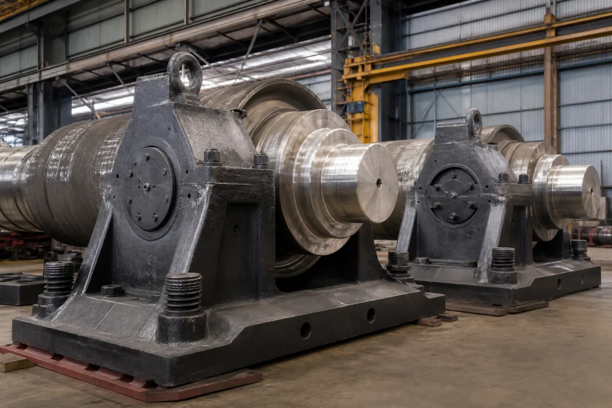
Roll chocks for four-row tapered roller bearings: how thick the chock wall must be, how the bearing sits loose on the neck, and when a worn chock bore has to be reworked
Bearing chocks on work and backup roll necks · chock wall sections as fractions of bearing O.D., loose neck fit and cone creep, chock bore rework limits, drainage and rocking supports
Every roll that goes into a flat mill stand goes in with a chock on each neck. The chock holds the roll-neck bearing, carries the rolling and bending loads into the stand, and comes out with the roll for every regrind, so it is handled, cleaned and measured in the roll shop at each roll change. Its own design questions are narrow and numerical: how much steel must surround the bearing, how the bearing is fitted so that the chock can be pulled off quickly, how the chock is drained and lubricated, and how far a chock bore may wear before it is reworked.
Roll chocks (bearing chocks, Einbaustücke) for work, intermediate and backup rolls of flat and long-product mills, with the four-row and two-row tapered roller bearings they carry, their neck fit, seals and drainage, wear and keeper plates, rocker supports, and chock bore inspection and rework. Complete stands, their stiffness and roll stacks are covered on the Heavy-duty rolling mill stand page; the frame on the Rolling mill housing (mill stand frame) page; rolls on the Rolling mill work roll and Backup rolls pages; roll-gap setting on the Hydraulic screwdown cylinder and Electromechanical screwdown mechanism pages; and the Steckel mill as a line on its own page.
CNFX editorial research · Sources checked October 13, 2026 · 3 sources
Chock wall sections of 0.0625 and 0.1 × bearing O.D., and the work-roll diameter they cost
Timken's metals-industry engineering manual gives the chock sections around a work-roll bearing as fractions of the bearing O.D.: a = 0.0625 × bearing O.D. and b = 0.1 × bearing O.D. for a symmetrical work roll chock. It says both the vertical and horizontal sections are critical to chock deflection and bearing performance. [1]
The reason is the bending load. Timken gives bending loads per chock in excess of 80 metric tons on cold mills and above 200 metric tons on hot mills, and says that with smaller chock sections a finite element analysis of the chock and bearing may be needed to validate the catalogue L10 life, because the chock bore deforms; the roller load then shows a 'rabbit ears' distribution, lower at the centre of the load zone than in the adjacent quadrants where the chock section is larger. [1]
The chock also limits how small the work roll may be ground. For a symmetrical chock Timken gives a minimum roll diameter of 1.125 × bearing O.D. + 2 mm; for a non-symmetrical chock, with the smaller section towards the pass line, 1.100 × bearing O.D. + 2 mm. [1] Editorial calculation for a 600 mm O.D. bearing: sections a = 37.5 mm and b = 60 mm; minimum work roll diameter 677 mm with a symmetrical chock and 662 mm with a non-symmetrical one, 15 mm more regrind allowance. The same manual puts the neck-to-barrel ratio at about 45–50% for cold mills with steel rolls and 55–60% for hot mills with cast iron rolls. [1]
Give the chock maker the bearing O.D., the roll's new and scrap diameters, the bending force per chock and whether the chock may be non-symmetrical about its centre line.
02
Loose fit on the neck, cone creep, 0.8 mm undercuts and drain slots for sealed bearings
Because the chock and bearing must be mounted and removed quickly at each work roll change, Timken states that a loose fit on the roll neck is standard practice at the work and intermediate roll positions regardless of rolling speed. With the neck smaller than the cone bore, the double cones creep round the neck; the cone turns at (roll neck diameter ÷ cone bore diameter) × roll rpm. [1]
For sealed roll-neck bearings Timken makes drain slots or holes between the chock seals and the bearing a requirement on both sides, to stop rolling solution or water pooling against the bearing's main seals, and asks for them to be inspected and cleared of trapped grease at each roll change. [1] Tight fits are used where speed demands: Timken's TDIT two-row assembly is mounted on a 1:12 taper for mill speeds up to 1,800 m/min, while the loose-fit TDIW suits roll speeds approaching 760 m/min; with tapered-bore tight fits the chock must float in the stand to accommodate the roll's thermal expansion. [1]
Roll changes also decide how the chock is clamped and lubricated. Danieli's patent EP 0 655 284 B1 describes clamping work-roll chocks axially to their sliding blocks with an oscillating lever that releases them for withdrawal towards the operator side, and lubricant connectors on the chock face that couple to connectors on the stand so that hoses need not be disconnected at each change; it notes that conventional trains use full-fill grease lubrication to avoid that delay. [3]
Item
Timken guidance for loose-fit four-row tapered bearings
Axial clearance at cones
Provided between cones and abutting faces so the cones creep freely [1]
Neck lubrication
Neck coated with the bearing lubricant; with air-oil, oil fed through cone-face slots and radial holes in the cone ribs [1]
0.8 mm on diameter, 1.6 mm beyond the tangency points beneath the cone spacer, 3.2 mm at the outer cone face [1]
Chock bore undercut
0.8 mm on diameter beneath each cup spacer; backup roll chocks only [1]
Fillet ring
Press fit on the neck, at least 0.00025 × bearing bore; seal seat plunge ground to 0.25–0.50 µm, 35 HRC minimum [1]
03
Chock bore rework limits by bearing O.D., keeper plates with a 2% slope, and chocks that must tilt
Timken asks for chock bores to be measured at each bearing inspection and at least once a year, polished free of corrosion and fretting, and, if reconditioned, reworked in sets of four to keep the four on the same mill centre line. Its table for inch-system bearings sets the bore against the nominal cup O.D.: [1]
Editorial calculation: for a bearing between 304.8 and 609.6 mm O.D., a bore that has grown from the new maximum of +0.152 mm to the reworked limit of +0.380 mm has worn 0.228 mm on diameter. Timken refers mills running tapered-bore bearings at 1,200 m/min or more to its engineers for these limits. [1]
The chock also has to rock with the roll. Timken describes keeper plates on the operator side and rocker plates under the backup roll chocks with a flat of 25% of the chock bore and a 2% slope either side, so that the chock follows roll and neck deflection, and asks for wear plates between work-roll chocks and backup-roll chock legs to be checked to prevent roll crossing and misalignment. [1] Morgan Construction's patent application EP 1 166 908 A2 explains the trade-off: cylindrical rocker plates let chocks tilt on line contact but need larger chocks for stiffness, spherical seats support more area but resist tilting through friction, and its answer is a curved chock base fed with pressurised lubricant so that a smaller chock can tilt freely. [2]
Record chock bore size, roundness and taper against the bearing maker's table at each inspection, and send chocks for rework as a set of four.
04
Data for roll chocks
Paste it into your enquiry below or into an email to a maker, then replace every bracket.
Mill and position: [hot or cold; work, intermediate or backup roll; operator or drive side]
Bearing: [type, e.g. four-row tapered TQOW or 2TDIW; bore; O.D.; sealed or open]
Loads: [roll force; bending force per chock; axial load]
Roll: [new and minimum diameter; neck diameter]
Chock: [symmetrical or non-symmetrical; material; bore tolerance]
Fittings: [end cover and bolt torque; seals; drain slots; lubrication: grease, oil mist or air-oil]
Stand interface: [wear and keeper plates; rocker plates; clamping to sliding blocks]
Service: [new chocks or rework of existing set of four]
Explore company information and manufacturing capabilities, then discuss the scope of your project with a relevant supplier.
Share this page
Compiled and source-reviewed by the CNFX editorial team.
Each manufacturer above links to the page on that company's own website where the product is listed, with the date we checked it. How we source and review
· Page last updated 13 October 2026
Buyer questions
How thick must a work roll chock be around the bearing?
Timken gives sections of 0.0625 × and 0.1 × bearing O.D. for a symmetrical work roll chock. [1]
Why are roll-neck bearings fitted loose?
For quick chock mounting and removal at frequent roll changes; Timken says the cones then creep on the neck, so the neck is lubricated and undercut. [1]
How far may a chock bore wear?
For 304.8–609.6 mm bearing O.D., Timken allows a reworked bore up to +0.380 mm over nominal cup O.D., 0.150 mm out of round and 0.050 mm taper. [1]
Why do chocks need to tilt?
Long flat-mill rolls bend under load, and the chocks must tilt so the bearing load spreads over its full length, as Morgan's EP 1 166 908 A2 explains. [2]
How are chocks lubricated without disconnecting hoses at every roll change?
Danieli's EP 0 655 284 B1 couples lubricant connectors on the chock face to connectors on the stand. [3]
Sources and what still needs a direct check
Sources checked 2026-10-13. Timken's Engineering Manual, Metals Industry Edition, Morgan Construction's patent application EP 1 166 908 A2 on tilting chock supports, and Danieli's patent EP 0 655 284 B1 on chock clamping and lubrication at roll change.