Editorial Technical Reference

Roll Gap Adjustment System

This page explains how Roll Gap Adjustment System is classified within Basic Metal Manufacturing. Technical values and manufacturer relationships are research references; confirm the current specification and supplier evidence for each order.

Technical Definition & Core Assembly

A precision control system that dynamically adjusts the distance between work rolls in a rolling mill to achieve desired material thickness and quality.
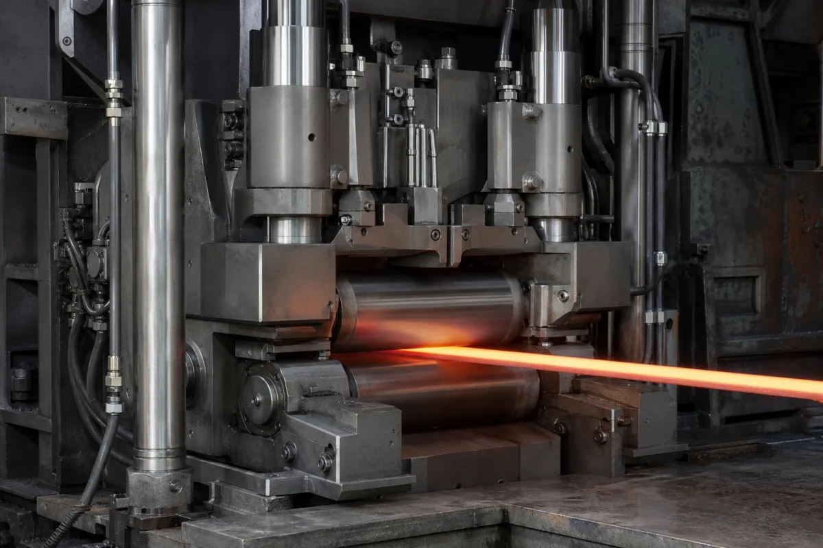
Representative product image. Confirm appearance and specifications with the manufacturer.

Product Specifications

Technical details and manufacturing context for Roll Gap Adjustment System

Definition
The Roll Gap Adjustment System is a critical component of a Multi-Stand Rolling Mill responsible for precisely controlling the gap between the work rolls at each stand. It ensures consistent material thickness, improves product quality by maintaining dimensional accuracy, and allows for rapid adjustments during rolling operations to accommodate different materials and thickness specifications. The system typically uses hydraulic cylinders, servo motors, or mechanical screws to apply controlled force to the roll chocks or bearing housings, thereby moving the rolls closer together or farther apart. Position sensors (e.g., linear encoders) provide real-time feedback to a control unit, which compares the actual roll gap to the target value and makes continuous adjustments to maintain precise gap settings throughout the rolling process. The system is designed for integration into existing mill control architectures, with a supply voltage of 24 V DC (±10%) and power consumption ranging from 0.5 to 2.0 kW. It operates within an ambient temperature range of -10°C to 60°C and a hydraulic fluid temperature range of -20°C to 80°C. The roll gap adjustment range is 0–10 mm, with an adjustment speed of 0.1–2.0 mm/s and positioning accuracy of ±0.01 mm. The system's ingress protection rating is IP54–IP65 (per IEC 60529), and its operating pressure is 1.0–1.6 MPa. Main structural components are made of 42CrMo4 (per DIN EN 10083-3), and the system weight varies from 500 to 2000 kg depending on configuration. Materials on file include high-strength alloy steel, hardened tool steel, and bronze bushings. These specifications serve as reference ranges; actual values must be confirmed with the legal manufacturer or supplier for the specific model and application.
Working Principle
The system adjusts the roll gap by applying controlled force via hydraulic cylinders, servo motors, or mechanical screws to the roll chocks or bearing housings. Position sensors, such as linear encoders, provide real-time feedback to a control unit. The control unit compares the measured gap to the target value and continuously adjusts the actuators to maintain the desired gap setting. This closed-loop control ensures precise thickness control and rapid response to changing process conditions.
Common Materials
High-strength alloy steel, Hardened tool steel, Bronze bushings
Technical Parameters
ParameterTypical rangeNotes & selection driver
Roll Gap Adjustment Range0–10 mmMaximum adjustment travel of the roll gap.
Adjustment Speed0.1–2.0 mm/sSpeed of roll gap adjustment.
Positioning Accuracy±0.01 mmAccuracy of roll gap positioning.
Operating Pressure1.0–1.6 MPa
Hydraulic Fluid Temperature-20–80 °COperating temperature range of hydraulic fluid.
Ambient Temperature-10–60 °COperating ambient temperature range.
Ingress ProtectionIP54–IP65Protection against dust and water.IEC 60529
Supply Voltage24 ±10% V DCControl system supply voltage.
Power Consumption0.5–2.0 kWTotal power consumption of the system.
Weight500–2000 kgSystem weight depending on configuration.
Material42CrMo4Material for main structural components.DIN EN 10083-3

Ranges are indicative industry figures for RFQ preparation, not a supplier commitment. Confirm every value and standard with the legal manufacturer before ordering.

Components / BOM
  • Hydraulic Cylinder Assembly
    Provides the force to move the rolls and adjust the gap
    Material: High-strength steel
  • Position Sensor
    Measures the actual roll gap position and provides feedback to the control system
    Material: Stainless steel housing with electronic components
  • Control Unit
    Processes sensor data and sends commands to adjust the roll gap based on target values
    Material: Electronic components in protective enclosure
  • Load Cell
    Measures the rolling force to ensure proper gap adjustment under load
    Material: Alloy steel with strain gauges
  • Mechanical Screw Optional
    The screw-down version of the gap drive, used instead of hydraulic capsules.

Applied To / Applications

This component is essential for the following industrial systems and equipment:

Industrial Ecosystem & Supply Chain Structure

Complementary Systems
Downstream Applications
Specialized Tooling

Application Fit & Sizing Matrix

Operational Limits
pressure: Max 300 bar hydraulic pressure, 10 bar pneumatic pressure
flow rate: Hydraulic: 20-100 L/min, Lubrication: 1-5 L/min
temperature: 0°C to 80°C (operational), -20°C to 100°C (storage)
response time: <50 ms for full adjustment
positioning accuracy: ±0.001 mm
Media Compatibility
✓ Hydraulic oil ISO VG 46 ✓ Water-glycol hydraulic fluids ✓ Synthetic rolling mill lubricants
Unsuitable: High-concentration abrasive slurry environments (e.g., steel descaling operations)
Sizing Data Required
  • Maximum rolling force (kN)
  • Required thickness tolerance (±mm)
  • Mill speed range (m/min)

Reliability & Engineering Risk Analysis

Failure Mode & Root Cause
Hydraulic Cylinder Seal Degradation
Cause: Contamination of hydraulic fluid with particulate matter leading to abrasive wear, or thermal degradation from excessive operating temperatures exceeding seal material limits.
Servo Motor/Encoder Feedback Failure
Cause: Electrical noise or voltage spikes disrupting control signals, or mechanical misalignment/vibration causing encoder disc damage or positional drift.
Maintenance Indicators
  • Audible: Unusual knocking or grinding noises during gap adjustment cycles, indicating mechanical interference or bearing failure.
  • Visual: Hydraulic fluid leaks around adjustment cylinder seals or fittings, or erratic/inaccurate gap readings on the control HMI despite calibration.
Engineering Tips
  • Implement a strict contamination control program for the hydraulic system, including regular fluid analysis and use of high-efficiency filtration to maintain ISO cleanliness codes.
  • Establish a predictive maintenance routine using vibration analysis on servo motors and periodic laser alignment checks of the roll and drive train to prevent misalignment-induced failures.

Indicative industry ranges for design and RFQ preparation. Confirm the exact figures and applicable standard with the manufacturer before specifying.

Compliance & Manufacturing Standards

Applicable Standards
ANSI B11.19 - Performance requirements for safeguarding CE Marking - Machinery Directive 2006/42/EC

Quoted from the published standard.

Manufacturing Precision
  • Roll gap parallelism: +/-0.01mm per meter
  • Frame alignment: 0.05mm total indicator runout
Quality Inspection
  • Laser alignment verification
  • Load cell calibration and repeatability testing

Manufacturers of Roll Gap Adjustment System

Manufacturer profiles associated with Roll Gap Adjustment System.

Sourcing Roll Gap Adjustment System from China?
Tell us your specification and target quantity — we will match it against manufacturer records and come back with the factories that fit.
Request manufacturers We manufacture this

Manufacturer listings support early research and capability understanding. They are not certification, ranking, or transaction guarantees.

Technical documentation
Request current drawings, revision history, and a signed specification sheet.
Manufacturing capability
Verify equipment lists, process limits, capacity, and representative production evidence.
Inspection readiness
Confirm test methods, calibrated equipment, sampling plans, and traceable reports.
Supplier transparency
Check the legal entity, factory address, ownership, certifications, and direct contacts.

CNFX does not score or rank suppliers. Buyers must verify all claims and documents with the legal manufacturer before ordering.

Supply Chain Compatible Machinery & Devices

Vacuum Induction Melting Furnace

Industrial furnace for melting metals under vacuum using electromagnetic induction

Explore Specs →
Electroslag Remelting Furnace

An industrial furnace used in basic metal manufacturing for secondary refining of alloys through the electroslag remelting (ESR) process.

Explore Specs →
Molten Metal Temperature Measurement System

Automated system for continuous temperature monitoring of molten metals during processing.

Explore Specs →
Molten Metal Degassing System

The Molten Metal Degassing System is an industrial system used in basic metal manufacturing to remove dissolved hydrogen, oxygen, and nitrogen from molten aluminum, steel, and other non-ferrous metals.

Explore Specs →

Frequently Asked Questions

What is the typical adjustment range of the roll gap?

The reference range is 0–10 mm, but the actual range depends on the specific mill configuration and must be confirmed with the manufacturer.

How does the system achieve high positioning accuracy?

It uses closed-loop control with position sensors (e.g., linear encoders) that provide real-time feedback to the control unit, enabling continuous adjustments to maintain the target gap.

What are the operating temperature limits?

The ambient temperature range is -10°C to 60°C, and the hydraulic fluid temperature range is -20°C to 80°C. These are reference values; verify for your application.

What standards apply to the system?

The operating pressure references ingress protection references IEC 60529, and material 42CrMo4 references DIN EN 10083-3. These are procurement references, not certifications.

Data Basis

Editorial classification, named public sources where available, and source-reviewed manufacturer records.

Preliminary Technical Classification
This page supports structured research, RFQ preparation, and supplier evaluation. It does not replace buyer-led supplier qualification, standards review, or technical approval.
Buyer enquiry

Request manufacturing insight for Roll Gap Adjustment System

Ask for use case, specification boundaries, supplier type, and RFQ preparation information for this product.

Where it goes
Straight to the CNFX editorial desk, and to the manufacturer if this product is linked to a claimed profile. Nothing is broadcast to a supplier list.
Your details stay here
We do not sell or rent enquiry data, and we do not add you to a mailing list. Used only to answer this request.
No commission, no middleman
CNFX is a directory. We take no cut of any order and never negotiate on a supplier's behalf.
What we don't claim
A listing is not an endorsement. Qualify every supplier and verify every figure yourself before ordering.

Your business information is used only to process this request.

Thank you! Your message has been sent. We'll respond within 1–3 business days.
Sorry, we couldn't send your message. Please try again, or email us at contact@cnfx.com.

Need to Manufacture Roll Gap Adjustment System?

Compare manufacturer profiles with relevant product and process capability.

Previous Product
Work Rolls
Last Product
Get QuotesChat