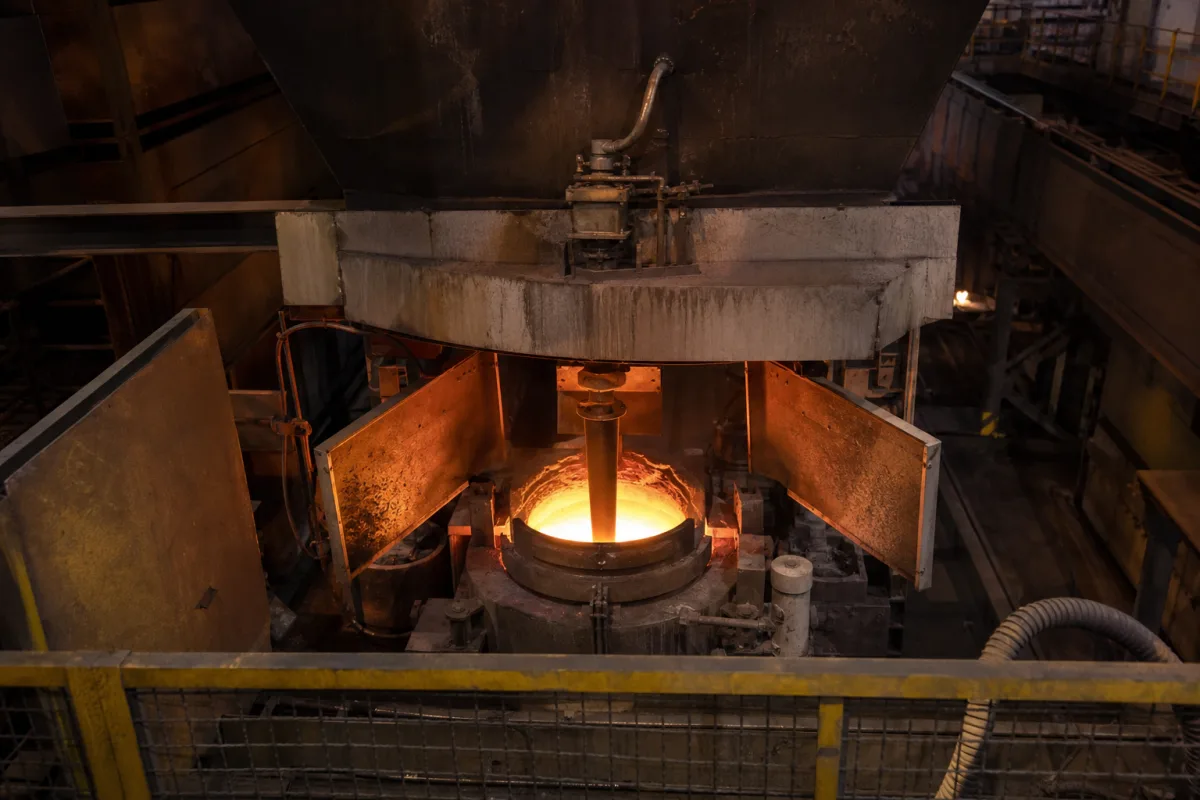
Submerged entry nozzle (SEN) for continuous casting
Continuous casting refractories · slag-line erosion and zirconia-graphite bands, alumina clogging, argon injection and bore geometry
A submerged entry nozzle (SEN) is the refractory tube that carries molten steel from the tundish into a continuous casting mould, with its lower end and ports submerged below the steel surface and the mould powder layer, so the stream is shielded from air and the flow in the mould is directed. Ask three things first: what slag-line material and thickness it has against the mould powder, how it resists alumina clogging for your steel grades, and what bore, port angle and submergence it is designed for.
Submerged entry nozzles (including submerged entry shrouds) for continuous casting of steel, in alumina-graphite and related refractories with zirconia-graphite slag bands, with or without argon injection. Ladle shrouds, tundish upper nozzles, stoppers, slide-gate plates and mould powder are outside this page except where they affect the SEN.
CNFX editorial research · Sources checked October 12, 2026 · 4 sources
US patent 5,656,192 (Didier-Werke, 1997) explains that SENs are made of alumina and graphite, the graphite giving thermal shock resistance when steel at about 1550 °C meets the nozzle, but weakening erosion resistance where the nozzle passes through the molten mould powder. It reports that a uniform alumina-graphite SEN (51% Al₂O₃ and 31% C in its example, within 40–65% and 20–35%) erodes at the slag line at 7 to 10 mm per hour in the patent's figures. [1]
A co-pressed zirconia-graphite band at the slag line (65–82% ZrO₂, 74% in its example, and 17–25% C, 20% in its example, bulk density 3.60 g/ml in its example) reduces erosion to 1.5 to 3.5 mm per hour, because the graphite needed for thermal shock still weakens the bond. A cemented sleeve of sintered zirconia erodes at only 0.2 to 0.5 mm per hour, but the patent calls it unacceptable in practice because of the risk of thermal shock failure, especially if preheating is not accurately controlled. [1]
Editorial calculation: if 15 mm of slag-line wall may be lost before the nozzle must be changed, a plain alumina-graphite nozzle at 7–10 mm/h lasts about 1.5–2.1 hours at the slag line, and a zirconia-graphite band at 1.5–3.5 mm/h about 4.3–10 hours. The 15 mm wear allowance is an assumed example; ask the supplier for slag-band thickness and measured erosion with your mould powder.
Give the supplier the caster type and section size, casting speed and throughput, steel grades and their aluminium, calcium and sulphur levels, mould powder, sequence length, tundish nozzle and stopper or slide-gate interface, bore and port design wanted, submergence depth, argon practice and preheating method.
02
Control alumina clogging with argon, steel practice and bore design
Rackers and Thomas (University of Illinois, 1995) describe clogging as build-up of deoxidation products such as alumina (1–20 μm particles in their report that sinter into a network), frozen steel, complex oxides drawn in with mould flux at the ports, and reaction products from air drawn in through porous refractory at negative pressure. Clogging forces the flow control to open further, can reduce casting speed or force a nozzle change, and dislodged clog can cause cleanliness defects. [2]
Argon injection through the nozzle wall or stopper, about 5 L/min (STP) in their report, is used to reduce clogging, by forming a gas film, flushing deposits and raising pressure to reduce air aspiration; its drawbacks include slag-line erosion from greater mould level fluctuation, bubbles trapped by the shell and nozzle cracking. Calcium treatment can liquefy alumina inclusions, but too little calcium can worsen clogging and it does not work for high-sulphur steels. Geometry measures reported include better joint sealing, a rounded entrance, a 5 mm annular internal step at mid-height and a flat-bottomed nozzle without a well. [2]
The paper notes that, at a fixed casting rate, turbulent pressure drop in a rough pipe is inversely proportional to the fifth power of the radius, so slide-gate position is a poor indicator of early clogging. [2] Editorial calculation: a 10 mm clog layer in an 80 mm bore reduces the radius from 40 to 30 mm, raising the pressure drop for the same flow by (40/30)⁵ ≈ 4.2 times. The clog thickness is an assumed example.
03
Specify zone compositions, pressing and bore profile
US patent 7,757,747 B2 (Submerged entry nozzle) describes a slab-caster SEN in which alumina graphite, magnesia graphite and zirconia graphite mixes are placed in their zones in an elastomeric mould and isostatically pressed together at pressures up to or above 4,000 psi, with the outside coated against oxidation during preheat. Its example compositions, with the balance being anti-oxidants and fluxes, are given below. [3]
The patent's bore changes from the circular inlet to a rectangular distribution zone through compression zones of 3–10% area reduction and diverging zones, which it says give the ports a stable steel column, and a flow-divider edge radius of at most 5 mm; the example SEN suits slabs about 50–230 mm thick and 610–1,520 mm wide. Compare its zirconia band composition with the 65–82% ZrO₂ range in the Didier-Werke patent above. [3][1]
Editorial calculation: 4,000 psi ≈ 27.6 MPa; a 3–10% reduction in a 5,152 mm² bore is about 155–515 mm².
Port geometry and immersion set the flow the SEN delivers into the mould. A 2023 study led by the University of Science and Technology Beijing modelled a 1,500 mm × 200 mm slab mould, validated by nail-board measurements on both sides of the SEN, using an industrial nozzle with a 58 mm inner diameter, 890 mm length, ports 55 mm high and 45 mm wide angled 15° down, a 130 mm submergence depth, 0.8 to 1.0 m/min casting speed and a 30 mm liquid slag layer. It found that standing-wave height on the top surface and its fluctuation rose with casting speed, that vortices formed in the low-speed zone next to the SEN, and that at 0.9 m/min the frequency distribution of level fluctuation peaked in the 2–6 mm range, highest at 3–4 mm. [4] Editorial note: give the supplier your mould size, casting speed range and target submergence so the port angle and size can be checked against surface-level behaviour.
Zone (US 7,757,747 example)
Material
Composition stated
Main body
Alumina graphite
About 65% Al₂O₃, 3% silica, 20% carbon
Wear-enhanced zones
Magnesia graphite
About 70% MgO, 3% silica, 19% carbon
Slag line band
Zirconia graphite
About 72% ZrO₂, 6% silica, 15% carbon
Overall length (example)
—
About 1,180 mm
Inlet bore (example)
—
81 mm diameter, about 5,152 mm²
Ask the supplier for zone compositions and band length, pressing method, oxidation coating, bore profile drawing and port design for your mould size.
04
SENs sold with tundish nozzles, ladle shrouds, stoppers and slide-gate plates
Listings include submerged entry nozzles alongside tundish nozzles, ladle shrouds, monoblock stoppers, slide-gate plates and zirconium sizing nozzles, with some offered as isostatically pressed refractories. Ask each for composition by zone, slag-band thickness, argon arrangement and preheating instructions.
05
Seating, body, bore, slag band, ports and argon channels
Two zones carry the failure modes this page starts from: the slag band against erosion at the mould powder, and the bore and ports against alumina clogging. [1][2]
Zone
Role
Fix in the order
Top seating or flange
Seals to the tundish nozzle; joint leaks draw in air. [2]
Bore, length, port angle, zone composition, density and porosity for an SEN order
The bore and length examples come from three different nozzles (80 mm and 840 mm in Rackers and Thomas's model, 58 mm and 890 mm in the 2023 slab study, 81 mm and about 1,180 mm in US 7,757,747), so size yours from your own throughput; refractoriness under load, cold crushing strength and weight have no published value here. [2][4][3]
Field
What it means and published values
Ask the supplier for
Nominal Bore Size (mm)
Examples modelled: 80 mm [2]; 58 mm at 0.8–1.0 m/min on a 1,500 × 200 mm slab. [4]
6 companies list this product among what they make. Company figures are quoted from each
company's own website; every card states where the relationship came from.
Shandong Zichuan Special Refractory
Manufacturing site to be confirmed for the order
Lists submerged entry nozzles for continuous casting, described as slag-resistant and anti-clogging.
Explore company information and manufacturing capabilities, then discuss the scope of your project with a relevant supplier.
Share this page
Compiled and source-reviewed by the CNFX editorial team.
Each manufacturer above links to the page on that company's own website where the product is listed, with the date we checked it. How we source and review
· Page last updated 13 October 2026
Buyer questions
How fast does an SEN erode at the slag line?
A Didier-Werke patent reports 7–10 mm/h for plain alumina-graphite and 1.5–3.5 mm/h with a zirconia-graphite band. [1]
Why do SENs clog?
Rackers and Thomas describe build-up of alumina deoxidation products, frozen steel, complex oxides from mould flux, and reaction products from aspirated air. [2]
How much argon is injected to prevent clogging?
Rackers and Thomas give “a typical injection rate” of 5 L/min (STP), with drawbacks including slag-line erosion and trapped bubbles. [2]
How is a multi-material SEN pressed?
US patent 7,757,747 describes placing alumina, magnesia and zirconia graphite mixes in their zones and isostatically pressing them together at up to or above 4,000 psi. [3]
What port geometry and submergence does a slab SEN use?
In a 2023 USTB study of a 1,500 × 200 mm slab mould, the industrial SEN had a 58 mm bore, 890 mm length, 55 × 45 mm ports angled 15° down and 130 mm submergence. [4]
Sources and what still needs a direct check
Sources checked 2026-10-12. The Didier-Werke patent describes prior-art and invented SEN constructions from a refractory maker's filing, and its erosion rates are the figures that filing reports; US 7,757,747 sets out zone compositions, pressing and bore profile for one slab-caster SEN. Rackers and Thomas is a peer-reviewed review of clogging from the University of Illinois Continuous Casting Consortium. The 2023 Materials paper (University of Science and Technology Beijing) models mould flow from an industrial SEN with stated port geometry.