Editorial Technical Reference

Aseptic Capping Unit

This page explains how Aseptic Capping Unit is classified within Beverage Manufacturing. Technical values and manufacturer relationships are research references; confirm the current specification and supplier evidence for each order.

Technical Definition & Core Assembly

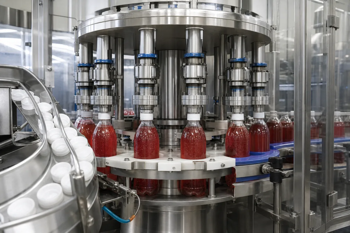
Aseptic capping unit for beverage production, applying sterile caps under controlled conditions.

Aseptic Capping Unit in a manufacturing environment
Representative product image. Confirm appearance and specifications with the manufacturer.

Product Specifications

Technical details and manufacturing context for Aseptic Capping Unit

Definition
The Aseptic Capping Unit is a critical component of an aseptic cold-fill beverage production system. Its primary function is to apply sterile caps or closures to pre-sterilized containers after filling, ensuring a hermetic seal that prevents microbial ingress and preserves product safety and shelf-life without thermal treatment after packaging. The unit operates within a controlled aseptic environment, often under HEPA-filtered laminar airflow or within an isolator, to maintain sterility throughout the capping process. It receives pre-sterilized caps, typically sterilized via hydrogen peroxide vapor, steam, or UV-C light, and containers from the aseptic filler. Using mechanical, pneumatic, or servo-driven mechanisms, it precisely picks, places, and secures the cap onto the container neck. Torque control is applied to achieve a consistent, hermetic seal. The entire process occurs within a zone maintained at positive pressure with sterile air to prevent airborne contamination. The unit is constructed from stainless steel (AISI 316L) with food-grade elastomers and ceramic coatings for durability and hygiene. Key parameters include capping speed of 12,000–24,000 cph, container diameter range of 50–110 mm, container height range of 120–320 mm, cap diameter range of 28–43 mm, capping torque of 1.5–4.5 N·m with accuracy of ±0.2 N·m, sterilization temperature of 121–134 °C and pressure of 0.2–0.3 MPa, operating pressure of 0.6–0.8 MPa (ISO 8573-1), electrical supply of 400 V AC ±10% (IEC 60038), power consumption of 5.5–7.5 kW, noise level ≤75 dB(A) (ISO 11201), weight of 2500–3500 kg, and degree of protection IP54–IP65 (IEC 60529). These values are reference ranges and must be verified for the specific model and application with the legal manufacturer or supplier. The unit is designed for integration into aseptic filling lines and requires proper validation of sterilization cycles and capping parameters to ensure product safety.
Working Principle
The unit receives pre-sterilized caps and containers from the aseptic filler. Caps are typically sterilized via hydrogen peroxide vapor, steam, or UV-C light. Using mechanical, pneumatic, or servo-driven mechanisms, the unit picks, places, and secures the cap onto the container neck. Torque control ensures a consistent, hermetic seal. The process occurs within a zone maintained at positive pressure with sterile air to prevent contamination.
Common Materials
Stainless Steel (AISI 316L), Food-grade elastomers, Ceramic coatings
Technical Parameters
ParameterTypical rangeNotes & selection driver
Capping Speed12000–24000 cphHigher speeds require larger turret and servo drives
Container Diameter Range50–110 mmOutside range requires change parts
Container Height Range120–320 mmAdjustable via starwheel and guide rails
Cap Diameter Range28–43 mmStandard beverage caps; other sizes on request
Capping Torque1.5–4.5 N·mAdjustable per cap and container
Torque Accuracy±0.2 N·mEnsures consistent seal integrity
Sterilization Temperature121–134 °CFor steam sterilization of capping head
Sterilization Pressure0.2–0.3 MPaOverpressure during sterilization cycle
Operating Pressure0.6–0.8 MPaCompressed air for pneumatic actuators
Electrical Supply400 ±10% V ACThree-phase, 50/60 HzIEC 60038
Power Consumption5.5–7.5 kWDepends on speed and servo configuration
Noise Level≤75 dB(A)At 1 m distance under loadISO 11201
Weight2500–3500 kgExcludes control cabinet and conveyor
Degree of ProtectionIP54–IP65IP65 for washdown areasIEC 60529

Ranges are indicative industry figures for RFQ preparation, not a supplier commitment. Confirm every value and standard with the legal manufacturer before ordering.

Components / BOM
  • Cap Hopper & Elevator
    Stores and feeds bulk sterile caps into the capping mechanism.
    Material: Stainless Steel
  • Cap Sorter/Orienter
    Aligns caps into the correct orientation for pickup.
    Material: Stainless Steel, Polycarbonate
  • Pick-and-Place Head
    Mechanism (mechanical gripper, vacuum suction, magnetic) that picks up a single oriented cap and places it onto the container.
    Material: Stainless Steel, Food-grade silicone
  • Spindle/Torque Head
    Applies controlled rotational force to screw the cap onto the container thread, ensuring consistent sealing torque.
    Material: Stainless Steel, Ceramic-coated components
  • Aseptic Chamber Enclosure
    Provides a physical barrier and maintains a sterile environment (e.g., with HEPA-filtered laminar airflow) around the capping process.
    Material: Stainless Steel, Polycarbonate viewing panels
  • Cap Sterilization Unit
    Sterilises the caps with peroxide vapour, steam or UV-C before they are picked.

Industrial Ecosystem & Supply Chain Structure

Complementary Systems
Downstream Applications
Specialized Tooling

Application Fit & Sizing Matrix

Operational Limits
pressure: 0.5 to 2.0 bar (capping force range)
flow rate: Up to 60,000 containers/hour (max throughput)
temperature: Ambient to 40°C (operating environment)
sterility class: ISO Class 5 (Grade A) cleanroom equivalent
Media Compatibility
✓ Carbonated beverages (CO2 atmosphere) ✓ High-acid juices (pH <4.6) ✓ Dairy-based drinks (UHT processed)
Unsuitable: Abrasive particulate suspensions (e.g., pulpy fruit blends with seeds)
Sizing Data Required
  • Container neck finish diameter (mm)
  • Required capping torque range (N·m)
  • Production line speed (containers/minute)

Reliability & Engineering Risk Analysis

Failure Mode & Root Cause
Seal degradation and leakage
Cause: Exposure to aggressive cleaning chemicals (CIP/SIP solutions), thermal cycling, and mechanical wear from repeated actuation, leading to loss of sterility barrier.
Actuator or drive mechanism failure
Cause: Misalignment, excessive mechanical load from jammed caps or foreign objects, or wear/fatigue in pneumatic cylinders, motors, or linkages, resulting in incomplete capping cycles.
Maintenance Indicators
  • Audible: Unusual grinding, knocking, or hissing sounds during operation, indicating mechanical binding, air leaks, or bearing wear.
  • Visual: Inconsistent cap placement, torque, or seal integrity on finished containers, or visible fluid leaks around the capping head or sterilization seals.
Engineering Tips
  • Implement a strict preventive maintenance schedule for seal inspection and replacement, using materials compatible with process chemicals, and validate sterilization cycles to prevent thermal stress.
  • Ensure precise mechanical alignment and calibration of capping heads, torque settings, and feed systems, and use sensors to detect jams or misfeeds early to avoid overload damage.

Indicative industry ranges for design and RFQ preparation. Confirm the exact figures and applicable standard with the manufacturer before specifying.

Compliance & Manufacturing Standards

Applicable Standards
ISO 13408-1: Aseptic processing of health care products ANSI/ASME BPE: Bioprocessing Equipment DIN EN 285: Sterilization - Steam sterilizers - Large sterilizers

Quoted from the published standard.

Manufacturing Precision
  • Capping torque: +/- 0.1 Nm
  • Sealing surface flatness: 0.05 mm
Quality Inspection
  • Sterility assurance level (SAL) validation
  • Helium leak test for integrity

Manufacturers of Aseptic Capping Unit

Manufacturer profiles associated with Aseptic Capping Unit.

Sourcing Aseptic Capping Unit from China?
Tell us your specification and target quantity — we will match it against manufacturer records and come back with the factories that fit.
Request manufacturers We manufacture this

Manufacturer listings support early research and capability understanding. They are not certification, ranking, or transaction guarantees.

Share this page
Technical documentation
Request current drawings, revision history, and a signed specification sheet.
Manufacturing capability
Verify equipment lists, process limits, capacity, and representative production evidence.
Inspection readiness
Confirm test methods, calibrated equipment, sampling plans, and traceable reports.
Supplier transparency
Check the legal entity, factory address, ownership, certifications, and direct contacts.

CNFX does not score or rank suppliers. Buyers must verify all claims and documents with the legal manufacturer before ordering.

Supply Chain Compatible Machinery & Devices

Automated Beverage Container Leak Detection System

The Automated Beverage Container Leak Detection System is an industrial device designed for integration into bottling or canning lines.

Explore Specs →
Automated Beverage Container Depalletizing Machine

Industrial machine that automatically removes beverage containers from pallets for production line feeding

Explore Specs →
Regeneration Section

A dedicated section within an industrial system designed to restore or renew the functional properties of materials, media, or components through controlled processes.

Explore Specs →
High-Speed Rotary Bottle Filling Machine

Automated industrial machine for precise liquid filling of beverage containers at high production rates.

Explore Specs →

Frequently Asked Questions

What is the typical capping speed range?

The reference range is 12,000 to 24,000 containers per hour (cph). Higher speeds may require a larger turret and servo drives. Confirm the exact speed for your model with the manufacturer.

What container sizes can this unit handle?

The reference ranges are 50–110 mm for container diameter and 120–320 mm for container height. Outside these ranges, change parts may be required. Verify compatibility with your containers.

How is sterility maintained during capping?

The unit operates in a controlled aseptic environment, often under HEPA-filtered laminar airflow or within an isolator. The zone is maintained at positive pressure with sterile air to prevent airborne contamination.

What are the electrical and utility requirements?

Electrical supply is 400 V AC ±10% (three-phase, 50/60 Hz) per IEC 60038. Operating pressure for pneumatic actuators is 0.6–0.8 MPa per ISO 8573-1. Power consumption is 5.5–7.5 kW. Confirm these with your facility's specifications.

Data Basis

Editorial classification, named public sources where available, and source-reviewed manufacturer records.

Preliminary Technical Classification
This page supports structured research, RFQ preparation, and supplier evaluation. It does not replace buyer-led supplier qualification, standards review, or technical approval.
Buyer enquiry

Request manufacturing insight for Aseptic Capping Unit

Ask for use case, specification boundaries, supplier type, and RFQ preparation information for this product.

Where it goes
Straight to the CNFX editorial desk, and to the manufacturer if this product is linked to a claimed profile. Nothing is broadcast to a supplier list.
Your details stay here
We do not sell or rent enquiry data, and we do not add you to a mailing list. Used only to answer this request.
No commission, no middleman
CNFX is a directory. We take no cut of any order and never negotiate on a supplier's behalf.
What we don't claim
A listing is not an endorsement. Qualify every supplier and verify every figure yourself before ordering.

Your business information is used only to process this request.

Thank you! Your message has been sent. We'll respond within 1–3 business days.
Sorry, we couldn't send your message. Please try again, or email us at [email protected].

Need to Manufacture Aseptic Capping Unit?

Compare manufacturer profiles with relevant product and process capability.

Previous Product
Vacuum Gripper End-Effector
Last Product
Get QuotesChat