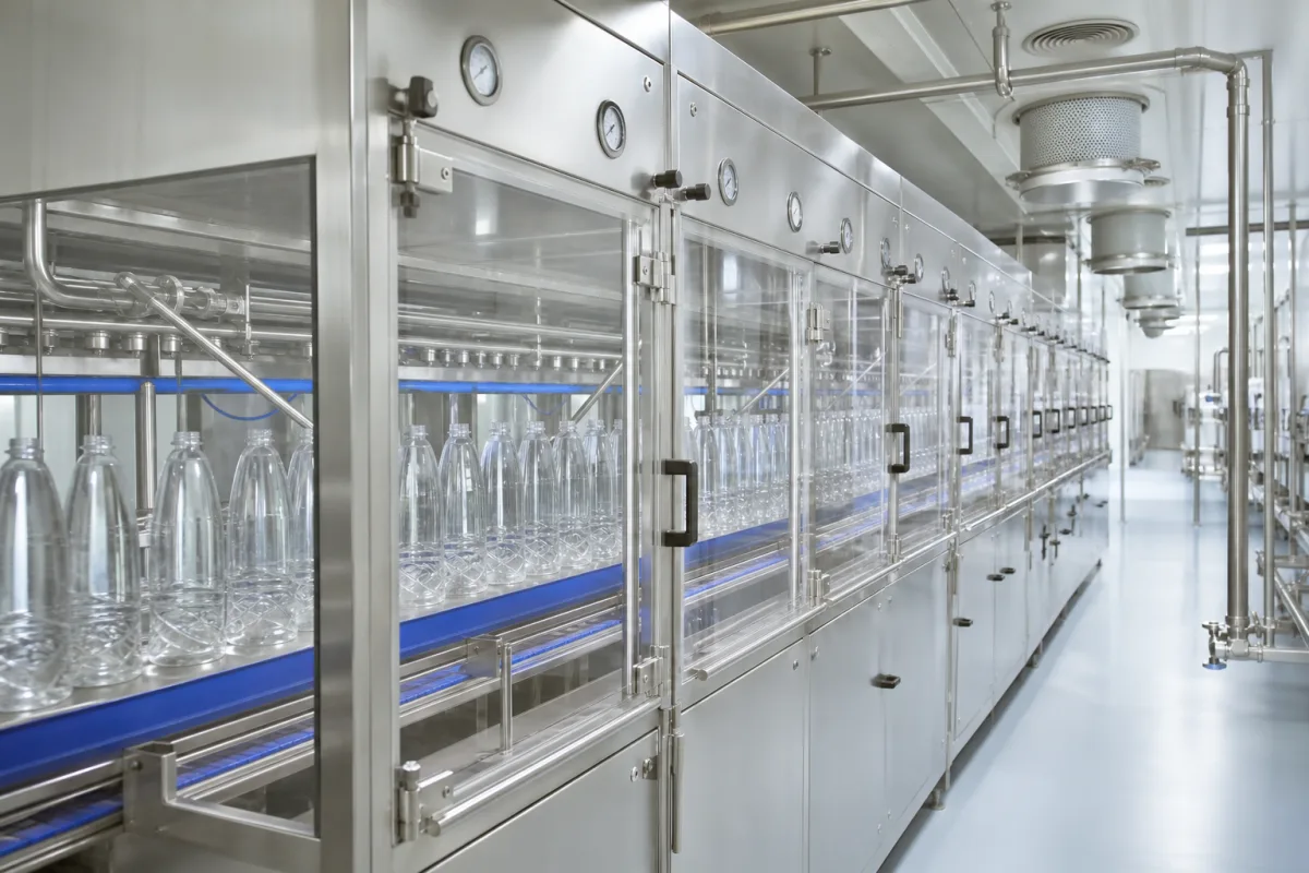
Sterile chamber and tunnel on an aseptic bottle filler: the pressure cascade, exit barrier and chamber decontamination
The enclosed, over-pressurised chambers that bottles pass through on an aseptic filler · pressure cascade from 20–40 Pa to atmosphere, the peroxide barrier chamber at the exit, ISO 5 air, and decontaminating the chamber walls
An aseptic filler does not sit in an open cleanroom: the bottles run through a tunnel of stainless-steel and glass chambers — sterilising, rinsing, filling, capping and discharge — each fed with sterile air and held at its own pressure so that air always flows from the cleanest chamber outwards. This page covers that enclosure as an engineered part of the machine: how the pressures step down, how the exit is sealed against the non-sterile room, what air quality is expected inside, and how the chamber surfaces are decontaminated.
Sterile chambers and tunnel enclosures (isolators) of aseptic beverage bottle fillers: the chain of chambers from sterilising to discharge, their pressure cascade and sterile-air supply, barrier and outlet chambers at the exit, interior air class, and chamber decontamination with peroxide gas or spray. Complete aseptic filling machines are covered on the Aseptic filling machine page; complete cold-fill PET lines with product sterilisers on the Aseptic cold-fill PET beverage line page; filling valves and their cores on the Aseptic filling valve and Aseptic beverage filling valve core pages; vial filling under RABS or isolators on the Pharmaceutical aseptic vial filling, stoppering and capping system page; isolators and RABS for sterile medicinal products on the Aseptic barrier: isolator and RABS page; the empty-bottle peroxide sterilizer on the Hydrogen peroxide bottle sterilizer for aseptic PET filling page; hot-water tunnels for filled containers on the Tunnel sterilizer (tunnel pasteurizer) page.
CNFX editorial research · Sources checked October 12, 2026 · 3 sources
Pressure cascade along the tunnel: highest in the filling chamber, atmospheric at the ends
US patent 11,261,072 (Dai Nippon Printing, priority 2016) describes the enclosed chambers of an aseptic PET bottle filler, each held at positive pressure: the pressure is highest in the filling portion chamber and steps down upstream through the air-rinsing chamber to the sterilising chamber, while an atmosphere shut-off chamber at the inlet is exhausted to about atmospheric pressure. [1]
FDA's 2004 guidance on aseptic processing of sterile drugs gives the room-scale equivalent: at least 10–15 Pa between adjacent rooms of differing classification with doors closed, and at least 12.5 Pa from an aseptic processing room to an unclassified neighbour. For isolators, FDA reports that differentials to the surrounding room “have largely ranged from approximately 17.5 to 50 Pascals” (0.07 to 0.20 inch water gauge), and that the air balance with interfaces such as a dry-heat tunnel should also be qualified. [3]
Editorial calculation: with a filling chamber at 20–40 Pa and an exhausted outlet at about 0 Pa, the whole cascade spans no more than 40 Pa — less than the upper end of FDA's 17.5–50 Pa isolator band — so each step between neighbouring chambers is a few pascals to a few tens of pascals and has to be measured and alarmed chamber by chamber, not only at the filler.
Ask for the design pressure of every chamber, the sensor at each, the alarm limits, and what the machine does — stop, close shutters, start re-sterilisation — when a step is lost.
02
The tunnel exit: a peroxide barrier chamber, an exhausted outlet and a washable discharge chamber
Capped bottles have to leave the sterile tunnel without letting room air in. In the DNP '072 design, a barrier chamber between the aseptic and non-aseptic zones is supplied with air containing hydrogen peroxide gas at 0.1 to 10 mg/L: below 0.1 mg/L is not enough to keep the chamber sterile, above 10 mg/L is excessive. Its pressure is kept below that of the filling chamber so the peroxide-laden air cannot flow back into it. [1]
Downstream, an outlet chamber is exhausted through a blower and a unit that detoxifies or collects the sterilant, and it counts as a non-aseptic zone: if a petaloid or unstable bottle falls over on the discharge conveyor there, a worker can lift it without stopping aseptic production. The peroxide for the barrier chamber can be taken from the exhaust of the sterilising chamber instead of a separate generator. [1]
Where bottles are discharged through an enclosed discharge portion chamber, the same patent sprays sterilant over its interior and then washes it with water sterilised at 121 °C or higher for at least 4 minutes, or through an aseptic filter, and sprayed at 60–100 °C through spin-ball nozzles, with its own aseptic air supply. [1] FDA likewise notes that a mousehole or exit port opens an isolator to the room, and that overpressure there should be supplied and monitored continuously. [3]
Ask how the exit is sealed (barrier chamber, air curtain, shutters), the sterilant concentration and how it is measured, where the exhaust is treated, and what happens to the aseptic zone when a bottle falls at the exit.
03
Air inside the chambers: ISO 5 at the open bottles, unidirectional flow at about 0.45 m/s
FDA's guidance places sterile containers exposed before closing in a critical area of Class 100 (ISO 5): no more than 3,520 particles of 0.5 µm and larger per cubic metre, measured near the exposed articles during activity, with an active-air action level of 1 cfu/m³. It cites an air velocity of 0.45 m/s (90 ft/min) with a range of ±20% around the setpoint, and says higher velocities may be appropriate in operations generating high levels of particulates. [3]
FDA distinguishes closed isolators, where turbulent flow can be acceptable, from isolators that house processing lines, where unidirectional air sweeps over and away from exposed sterile materials once and is then exhausted; as an example of suitable materials it names rigid wall construction in stainless steel and glass. [3]
Editorial calculation: 0.45 m/s ±20% is a window of 0.36 to 0.54 m/s at the working height. Editorial note: these are FDA recommendations for sterile drugs, which beverage aseptic filler makers and buyers use as a reference; a beverage plant's own requirement comes from its process authority and food regulations.
At least 12.5 Pa from the aseptic processing room [3]
04
Decontaminating the chamber walls and nozzles between production runs
US patent 11,186,474 (Dai Nippon Printing, priority 2017), on decontaminating an aseptic filling apparatus, reports that the outside of the filling nozzles is readily sterilised when the hydrogen peroxide gas in the chamber is at least 5 mg/L and the filling valves are at 60 °C or above, even with nozzles that have been at 130 °C during product-path sterilisation. [2]
The same patent runs the product path through cleaning at about 80 °C for 20 minutes, for example, then SIP with hot water at 95 °C, and gives sterilisation conditions by product acidity: at least 60 °C for 10 minutes below pH 4, 85 °C for 30 minutes at pH 4.0 to 4.6, and 120 °C for at least 4 minutes at pH 4.6 and above, as examples of SIP conditions set by the product. [2]
For isolators, FDA asks that the decontamination cycle reach all interior surfaces — gloves fully extended with fingers separated — and says a four- to six-log reduction of a biological indicator “can be justified depending on the application”, with a six-log reduction where decontamination, not heat, is used on product contact surfaces. A breach of integrity, such as a power failure, valve failure, inadequate overpressure or a holed glove, should lead to a new decontamination cycle. [3]
Ask for the chamber decontamination method and concentration, the biological-indicator log reduction validated, the cycle time from end of production to sterile restart, and the list of events that force a re-sterilisation.
05
What to send for a sterile chamber or tunnel
Paste it into your enquiry below or into an email to a maker, then replace every bracket.
Line: [bottle type and sizes; speed; product pH class]
Chambers: [sterilising, rinsing, filling, capping, discharge; lengths]
Pressures: [design value per chamber; sensors; alarms]
Air: [HEPA supply; class at open bottles; velocity]
Exit: [barrier chamber or other seal; sterilant and exhaust treatment]
Decontamination: [method; concentration; temperature; log reduction; cycle time]
Access: [glove ports; doors and interlocks]
Utilities: [sterile air; steam; sterile water; exhaust]
Explore company information and manufacturing capabilities, then discuss the scope of your project with a relevant supplier.
Share this page
Compiled and source-reviewed by the CNFX editorial team.
Each manufacturer above links to the page on that company's own website where the product is listed, with the date we checked it. How we source and review
· Page last updated 13 October 2026
Buyer questions
What pressure is kept in the filling chamber of an aseptic bottle filler?
A DNP patent gives 20–40 Pa as an example, with lower pressures in the barrier (preferably 0–30 Pa) and discharge (10–30 Pa) chambers and an exhausted outlet near 0 Pa. [1]
Why is there a peroxide barrier chamber at the exit?
In DNP's design it separates aseptic and non-aseptic zones with air carrying 0.1–10 mg/L of hydrogen peroxide gas, so a bottle that falls in the outlet can be lifted without breaking sterility. [1]
What air class is expected inside an aseptic chamber?
FDA's aseptic guidance expects Class 100 (ISO 5) inside isolators, with 0.45 m/s ±20% cited for air velocity in critical areas. [3]
How are the chamber surfaces decontaminated?
A DNP patent sterilises nozzle exteriors with at least 5 mg/L of peroxide gas in the chamber and valves at 60 °C or more; FDA cites four- to six-log reductions for isolator decontamination. [2][3]
Sources and what still needs a direct check
Sources checked 2026-10-12. Chamber pressures, the exit barrier and discharge-chamber washing come from US patent 11,261,072, and chamber decontamination and SIP conditions from US patent 11,186,474, both assigned to Dai Nippon Printing; air class, velocity, pressure differentials and isolator decontamination from FDA's 2004 guidance for sterile drug products produced by aseptic processing.