Editorial Technical Reference

Dust Containment System

This page explains how Dust Containment System is classified within Chemical Manufacturing. Technical values and manufacturer relationships are research references; confirm the current specification and supplier evidence for each order.

Technical Definition & Core Assembly

A safety and environmental control system designed to capture, contain, and prevent the escape of airborne pharmaceutical powder particles during blending operations.
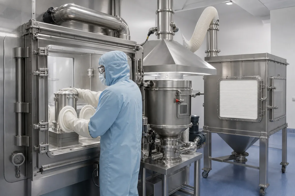
Dust Containment System in a manufacturing environment
Representative product image. Confirm appearance and specifications with the manufacturer.

Product Specifications

Technical details and manufacturing context for Dust Containment System

Definition
The Dust Containment System is an integral safety component of the Automated Pharmaceutical Powder Blender that prevents cross-contamination, protects operator health, and maintains cleanroom compliance by actively capturing and filtering airborne particulate matter generated during powder mixing, transfer, and discharge processes. It operates on negative pressure differentials, HEPA/ULPA filtration, and sealed enclosures to create containment zones at source points, ensuring that hazardous dust does not escape into the surrounding environment. The system is constructed from Stainless Steel 316L, food-grade plastics, and HEPA/ULPA filter media, offering durability and compatibility with pharmaceutical processes. Key parameters include an airflow rate of 500–2000 m³/h, filter efficiency of 99.99–99.999% (ISO 16890), containment level OEB4–OEB5 (ISPE SMEPAC), noise level 65–75 dB(A) (ISO 3744), operating pressure 1.0–1.6 MPa, operating temperature 0–60°C, relative humidity 30–85% RH (non-condensing), ingress protection IP54–IP65 (IEC 60529), power supply 380–480 V AC three-phase 50/60 Hz (IEC 60038), power consumption 2.2–7.5 kW, material SS304/SS316L (ASTM A240), weight 150–500 kg, and footprint 1.2–2.5 m². These values are reference ranges and must be verified for the specific model and application. The system is designed for integration into blending operations, with interfaces for process control and monitoring. Maintenance signals include increased pressure drop across filters, reduced airflow, or audible alarms. Failure boundaries include filter degradation above 60°C and non-condensing humidity limits. Always confirm model-specific values and standards with the legal manufacturer or supplier.
Working Principle
The system uses negative pressure differentials to create a containment zone around powder handling points. Airborne particles are captured at the source through hoods or enclosures, then drawn through HEPA/ULPA filters that remove 99.99–99.999% of particles. Sealed enclosures prevent fugitive emissions, while the filtered air is recirculated or exhausted safely. The negative pressure ensures that any leak flows inward, protecting operators and the environment.
Common Materials
Stainless Steel 316L, Food-Grade Plastics, HEPA/ULPA Filter Media
Technical Parameters
ParameterTypical rangeNotes & selection driver
Airflow RateRequired500–2000 m³/hVolume of air processed by the containment system per hour
Filter EfficiencyRequired99.99–99.999 %Particle capture efficiency at specified micron sizeISO 16890
Containment LevelRequiredOEB4–OEB5 OEBOccupational Exposure Band classification for contained substancesISPE SMEPAC
Noise Level65–75 dB(A)Maximum operating noise at 1 meter distanceISO 3744
Operating Temperature0–60 °CAbove 60°C filter media degrades
Relative Humidity30–85 % RHNon-condensing
Ingress ProtectionIP54–IP65Dust-tight and water-resistantIEC 60529
Power Supply380–480 V ACThree-phase, 50/60 HzIEC 60038
Power Consumption2.2–7.5 kWDepends on airflow and pressure drop
MaterialSS304/SS316LContact parts; 316L for corrosiveASTM A240
Weight150–500 kgVaries with configuration
Footprint1.2–2.5 Length × width

Ranges are indicative industry figures for RFQ preparation, not a supplier commitment. Confirm every value and standard with the legal manufacturer before ordering.

Components / BOM
  • Containment Hood
    Primary enclosure that surrounds powder handling points to capture airborne particles at source
    Material: Stainless Steel 316L with transparent viewing panels
  • HEPA/ULPA Filter Unit
    High-efficiency particulate air filter that removes airborne particles from the containment airflow
    Material: Glass fiber or PTFE filter media in aluminum housing
  • Exhaust Fan Assembly
    Creates negative pressure within the containment system to draw air through filters
    Material: Stainless Steel housing with corrosion-resistant impeller
  • Ducting System
    Transports contaminated air from containment points to filtration unit
    Material: Stainless Steel or food-grade flexible tubing
  • Pressure Monitoring System
    Monitors pressure differentials to ensure proper containment performance
    Material: Electronic sensors with stainless steel fittings

Industry Taxonomies & Aliases

Commonly used trade names and technical identifiers for Dust Containment System.

Industrial Ecosystem & Supply Chain Structure

Complementary Systems
Downstream Applications
Specialized Tooling

Application Fit & Sizing Matrix

Operational Limits
pressure: Max 0.5 bar (7.25 psi) differential
flow rate: Up to 500 m³/h (294 CFM) per module
temperature: Ambient to 40°C (104°F)
slurry concentration: Not applicable - dry powder system only
Media Compatibility
✓ Pharmaceutical active ingredients (APIs) ✓ Excipients (lactose, microcrystalline cellulose) ✓ Food-grade powders (starch, flavorings)
Unsuitable: High-moisture or hygroscopic materials requiring inert gas blanketing
Sizing Data Required
  • Blender vessel volume (liters)
  • Required containment efficiency (e.g., 99.97% @ 0.3 microns)
  • Maximum powder transfer rate (kg/h)

Reliability & Engineering Risk Analysis

Failure Mode & Root Cause
Filter Media Degradation
Cause: Excessive particulate loading beyond design capacity, leading to filter blinding, increased pressure drop, and eventual rupture or bypass leakage.
Fan/Motor Bearing Failure
Cause: Dust ingress into bearing housings due to inadequate sealing, combined with imbalance from dust accumulation on fan blades, causing overheating and premature wear.
Maintenance Indicators
  • Abnormally high system pressure drop (indicated on gauges) accompanied by audible straining of the fan motor.
  • Visible dust leakage around filter seals, housing joints, or duct connections, indicating seal failure or filter breach.
Engineering Tips
  • Implement a differential pressure monitoring system with automated alerts to trigger filter cleaning/replacement before overloading occurs.
  • Establish a routine inspection and cleaning schedule for fan blades, bearings, and seals, using vibration analysis to detect early imbalance or bearing wear.

Indicative industry ranges for design and RFQ preparation. Confirm the exact figures and applicable standard with the manufacturer before specifying.

Compliance & Manufacturing Standards

Applicable Standards
ISO 14644-1:2015 Cleanrooms and associated controlled environments ANSI/ASHRAE 52.2-2017 Method of Testing General Ventilation Air-Cleaning Devices for Removal Efficiency by Particle Size DIN EN 1822-1:2019 High efficiency air filters (EPA, HEPA and ULPA)

Quoted from the published standard.

Manufacturing Precision
  • Filter Frame Squareness: +/-0.5°
  • Sealing Surface Flatness: 0.2mm over 1m length
Quality Inspection
  • HEPA/ULPA Filter Leak Test (EN 1822-5)
  • Airflow Uniformity Test (ISO 14644-3)

Manufacturers of Dust Containment System

Manufacturer profiles associated with Dust Containment System.

Sourcing Dust Containment System from China?
Tell us your specification and target quantity — we will match it against manufacturer records and come back with the factories that fit.
Request manufacturers We manufacture this

Manufacturer listings support early research and capability understanding. They are not certification, ranking, or transaction guarantees.

Share this page
Technical documentation
Request current drawings, revision history, and a signed specification sheet.
Manufacturing capability
Verify equipment lists, process limits, capacity, and representative production evidence.
Inspection readiness
Confirm test methods, calibrated equipment, sampling plans, and traceable reports.
Supplier transparency
Check the legal entity, factory address, ownership, certifications, and direct contacts.

CNFX does not score or rank suppliers. Buyers must verify all claims and documents with the legal manufacturer before ordering.

Supply Chain Compatible Machinery & Devices

Automated pH Monitoring and Dosing System

Automated system for continuous pH monitoring and chemical dosing in process streams.

Explore Specs →
Automated Powder Dispensing and Blending System

Automated system for precise dispensing and homogeneous blending of powdered chemicals.

Explore Specs →
Automated Viscosity Control and Mixing System

The Automated Viscosity Control and Mixing System is an industrial automation solution designed for continuous monitoring and adjustment of viscosity in chemical mixing and blending operations.

Explore Specs →
Automated Catalyst Loading and Unloading System

The Automated Catalyst Loading and Unloading System is an integrated automation solution for the precise and safe transfer of catalyst materials in fixed-bed reactors, continuous stirred-tank reactors, and other catalytic process vessels.

Explore Specs →

Frequently Asked Questions

What is the typical airflow rate range for this dust containment system?

The airflow rate is typically in the range of 500 to 2000 m³/h, but the exact value depends on the specific model and application. Always verify with the manufacturer.

What filter efficiency does the system provide?

The filter efficiency is 99.99% to 99.999% at specified micron sizes, tested according to ISO 16890. This ensures high capture of airborne particles.

What containment levels are achievable?

The system is designed to achieve OEB4 to OEB5 containment levels as per ISPE SMEPAC guidelines, suitable for highly potent pharmaceutical compounds.

What are the operating temperature and humidity limits?

The operating temperature range is 0 to 60°C, and relative humidity should be 30% to 85% RH (non-condensing). Exceeding these limits may degrade filter media or affect performance.

Data Basis

Editorial classification, named public sources where available, and source-reviewed manufacturer records.

Preliminary Technical Classification
This page supports structured research, RFQ preparation, and supplier evaluation. It does not replace buyer-led supplier qualification, standards review, or technical approval.
Buyer enquiry

Request manufacturing insight for Dust Containment System

Ask for use case, specification boundaries, supplier type, and RFQ preparation information for this product.

Where it goes
Straight to the CNFX editorial desk, and to the manufacturer if this product is linked to a claimed profile. Nothing is broadcast to a supplier list.
Your details stay here
We do not sell or rent enquiry data, and we do not add you to a mailing list. Used only to answer this request.
No commission, no middleman
CNFX is a directory. We take no cut of any order and never negotiate on a supplier's behalf.
What we don't claim
A listing is not an endorsement. Qualify every supplier and verify every figure yourself before ordering.

Your business information is used only to process this request.

Thank you! Your message has been sent. We'll respond within 1–3 business days.
Sorry, we couldn't send your message. Please try again, or email us at [email protected].

Need to Manufacture Dust Containment System?

Compare manufacturer profiles with relevant product and process capability.

Previous Product
Twin-Screw Polymer Compounding Extruder
Last Product
Get QuotesChat