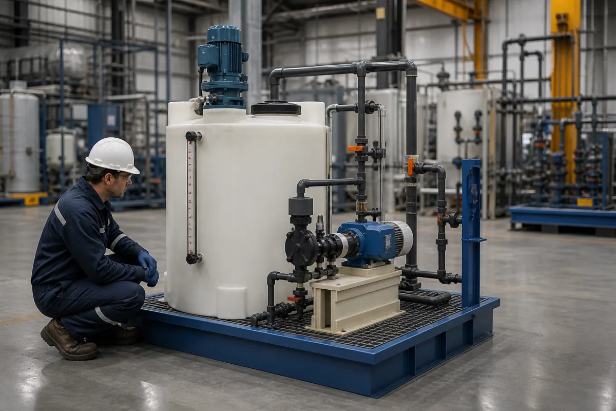
Chemical day tank with mixer and metering pump: the solution tank, its sizing and the suction side of a liquid chemical feed set
The tank half of a chemical feed set · day tank capped at a 30-hour supply, translucent polyethylene rated by specific gravity, mixer, calibration cylinder on the pump suction, and containment for 110% of the largest tank
In a liquid chemical feed set the metering pump gets the attention, but the tank it draws from decides how accurately the dose can be checked, how long a batch of solution sits, and what happens when something leaks. Water-works design standards treat that tank as equipment in its own right: how much it may hold, how its level is read, how the solution is kept uniform, how the pump suction is arranged, and how spills are contained.
Chemical solution and day tanks that feed a metering pump, supplied with or without the pump as a tank-and-pump set: tank sizing, polyethylene tank rating, level gauges and scales, mixers, suction fittings, calibration cylinders, filling and spill containment. Packaged duty/standby dosing pump skids are covered on the Chemical dosing pump skid page; choosing the metering pump on the Metering pump page; reagent feed skids for continuous reactors on the Reagent feed system page; bulk reagent storage on the Reagent storage tank page; centrifugal and other process pumps on the Industrial pumps page.
CNFX editorial research · Sources checked October 12, 2026 · 4 sources
How big: no more than a 30-hour supply in a day tank, a week in a small-system solution tank
The Recommended Standards for Water Works (the Ten States Standards, 2018 edition) require a day tank wherever liquid chemical is stored in bulk — the reviewing authority may allow feeding straight from shipping containers of 55 gallons or less — and say a day tank should hold no more than a 30-hour supply at average-day demand. [1] Connecticut's Department of Public Health uses the same 30-hour maximum for day tanks, 30 days for bulk tanks, and notes that small groundwater systems use a solution tank of 30–55 gallons sized for about one week of solution. [2]
Editorial calculation, using Connecticut's small-system formula with assumed values: a 50 gpm well dosed at 2 ppm from a 1% (10,000 ppm) solution needs 50 × 2 × 1,440 ÷ 10,000 = 14.4 gal/day, or 0.6 gal/h. A week's supply is about 101 gal, more than a 55-gal tank, so either the solution is made stronger or the tank larger; a 30-hour day tank for the same duty would hold 18 gal. A pump rated about 1.2 gal/h would put 0.6 gal/h near mid-setting.
Connecticut sizing step
Formula or rule
Feed rate, large systems
lb/day = dose (mg/L) × flow (MGD) × 8.34, divided by the chemical's strength as a decimal [2]
Calculated rate near mid-setting, e.g. 50% stroke and speed on a diaphragm pump [2]
Day tank
Maximum 30 hours at average dose and average daily demand [2][1]
Small-system solution tank
About one week of solution; tanks of 30–55 gal [2]
Give the tank supplier the chemical and its strength, average and maximum daily use, whether the tank is a day tank fed from bulk or a batch-mixed solution tank, and the pump's maximum rate.
02
The tank: a gauge you can read, a cover and vent, and a wall rated for the solution's specific gravity
Ten States requires day tanks to be scale-mounted or to carry a calibrated gauge where the level can be seen in a gauge tube or through a translucent wall (a gauge rod in opaque tanks), to have a means of keeping the chemical strength uniform — continuous agitation for slurries — and to be labelled at the tank and fill point; filling of day tanks is not to be automated unless the reviewing authority allows it. [1] Connecticut adds screened outside vents, overflows and drains, covers against dust and insects, and outlets 6–12 in above the floor for chemicals that may crystallise. [2]
For polyethylene tanks, Poly Processing explains that the wall is designed for the chemical's specific gravity, operating temperature and oxidation potential; it builds standard tanks for specific gravities of 1.35, 1.65, 1.9 and 2.2, advises limiting standard tanks to 100 °F, and quotes walls from 0.15 in to 2 in or more depending on size and position. A tall, narrow tank needs a thicker bottom sidewall than a short, wide one holding the same chemical. [3] It states that ASTM D1998 has the designer de-rate resin strength by 50%, so a resin rated at 1,200 psi hoop stress is designed at 600 psi. [4]
Editorial note: a tank labelled for 1.9 specific gravity is not automatically right for a warm or strongly oxidising solution such as sodium hypochlorite; ask for the wall-thickness data sheet for the actual diameter, height and chemical.
Specify tank material and specific gravity rating, maximum temperature, gauge or scale, cover, vent, overflow and drain, outlet height, mixer mounting, and labelling.
03
Between tank and pump: flooded suction, a foot valve 3–6 in off the floor, a calibration cylinder vented to the tank
Connecticut's guideline lists the suction-side fittings: run diaphragm pumps with a flooded suction where possible, particularly for off-gassing chemicals such as sodium hypochlorite; keep suction lines short and straight without loops; fit strainers; and where a pump works on suction lift, put a foot valve 3–6 in above the tank bottom so solids do not reach the pump. A calibration cylinder between the solution tank and the pump, vented to the day tank, allows routine checks of pump output. [2]
On the discharge side it calls for a pressure relief valve discharging to the day tank, a back-pressure valve, a bleed valve back to the tank, pulsation dampeners and a check valve at the injection point. [2] Ten States asks for positive-displacement solution pumps for liquid chemicals (not slurries), sized for the maximum rate against the maximum head at the injection point, with calibration tubes or mass flow monitors and a relief valve on the discharge. [1]
Editorial note: each of those return lines — relief, bleed and calibration-cylinder vent — needs a tank connection; agree the number and size of nozzles on the tank top before it is moulded.
04
Spills and filling: containment for 110% of the largest tank, and a deadman control on transfers
Connecticut asks that containment hold the full amount of chemical stored where feasible, and at minimum 110% of the volume of the largest storage tank; transfers from bulk tanks to day tanks should have a fail-safe deadman switch or valve. [2] Ten States requires secondary containment able to hold the largest storage tank, a shared receiving basin only for each group of compatible chemicals, and a level limit switch where motor-driven transfer pumps fill from shipping containers. [1]
Editorial calculation: for a single 55-gal solution tank, 110% is about 60.5 gal of containment; a skid-mounted bund for that tank needs at least that much volume below its grating or lip.
Ten States also requires separate day tanks and feeders for feed points ahead of and after filtration when no other cross-connection control is provided. [1]
State the containment volume required (100% or 110% of the largest tank), which chemicals may share it, and how the day tank is filled.
05
What to send for a chemical feed tank and pump set
Paste it into your enquiry below or into an email to a maker, then replace every bracket.
Chemical: [name; strength; specific gravity; temperature; off-gassing or crystallising]
Use: [average and maximum daily volume; day tank or batch solution tank]
Tank: [volume; material and SG rating; gauge or scale; mixer; vent, overflow, drain; outlet height]
Pump side: [flooded suction or lift; foot valve; strainer; calibration cylinder; return nozzles]
Containment: [volume; shared or separate]
Filling: [manual, transfer pump with limit switch, deadman]
Explore company information and manufacturing capabilities, then discuss the scope of your project with a relevant supplier.
Share this page
Compiled and source-reviewed by the CNFX editorial team.
Each manufacturer above links to the page on that company's own website where the product is listed, with the date we checked it. How we source and review
· Page last updated 13 October 2026
Buyer questions
How large should a chemical day tank be?
The Ten States Standards say no more than a 30-hour supply at average-day demand; Connecticut uses the same maximum. [1][2]
How is the feed rate checked?
With a calibration cylinder between the tank and the metering pump, vented to the day tank, or calibration tubes or mass flow monitors. [2][1]
What specific gravity rating should a polyethylene tank have?
It depends on the chemical and temperature; Poly Processing builds standard tanks for 1.35, 1.65, 1.9 and 2.2 and advises a 100 °F limit for standard tanks. [3]
How much spill containment is needed?
Connecticut asks for at least 110% of the largest tank; Ten States requires the volume of the largest storage tank. [2][1]
Sources and what still needs a direct check
Sources checked 2026-10-12. Day-tank, gauge, agitation, pump and containment rules come from the 2018 Recommended Standards for Water Works and the Connecticut Department of Public Health's liquid chemical feed guidelines, both written for drinking-water plants; polyethylene tank ratings and ASTM D1998 de-rating from Poly Processing, a tank maker.