Editorial Technical Reference

Gas Injection System

This page explains how Gas Injection System is classified within Chemical Manufacturing. Technical values and manufacturer relationships are research references; confirm the current specification and supplier evidence for each order.

Technical Definition & Core Assembly

A system designed to introduce and distribute gases into a refining vessel for process control, mixing, or chemical reactions.
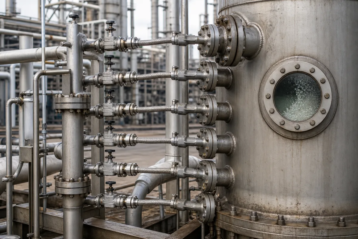
Representative product image. Confirm appearance and specifications with the manufacturer.

Product Specifications

Technical details and manufacturing context for Gas Injection System

Definition
The Gas Injection System is a critical component of a Refining Vessel responsible for the controlled introduction, distribution, and sometimes recirculation of process gases (such as hydrogen, nitrogen, or reactive gases) into the vessel's contents. Its primary role is to facilitate chemical reactions, improve mixing, control pressure, purge unwanted vapors, or create specific atmospheric conditions necessary for the refining process. The system typically consists of a gas source, pressure regulators, control valves, flow meters, and an injection manifold or sparger (a perforated pipe or diffuser) located within the vessel. Gas is fed from a supply line, its flow and pressure are precisely controlled, and it is then injected through the sparger, which disperses the gas as fine bubbles or a directed stream into the liquid or solid medium inside the vessel to achieve the desired process effect. This directory entry provides reference specifications for selection and verification. The system is designed for use in chemical manufacturing environments, with materials of construction including stainless steel (e.g., 316L), alloy steel, and high-grade plastics (e.g., PTFE for linings). Key parameters include operating pressure of 1.0–1.6 MPa (per note:), gas flow rate of 50–500 Nm³/h per injection point, injection accuracy of ±1.5% of setpoint, response time of ≤2 seconds from signal to full stroke, operating temperature of -20–80°C for process media, ambient temperature of -10–60°C for control unit, supply voltage of 24 ±10% V DC for actuators and sensors, power consumption of ≤120 W peak, ingress protection of IP54–IP65 (per IEC 60529) for outdoor installation, wetted parts material of 316L (per ASTM A240), connection size of DN25–DN100 (flange or threaded, per ISO 7005), and weight of 15–60 kg depending on configuration. These values are reference ranges and must be confirmed for the specific model and application with the legal manufacturer or supplier. The system is a component, not a standalone product, and its performance depends on integration with the refining vessel and process conditions. Verification questions should address compatibility with the process gas, vessel design, and control system. Maintenance signals include pressure drops, flow inconsistencies, or leakage. Failure boundaries include operation outside specified pressure, temperature, or flow ranges, which may lead to inadequate gas distribution or safety hazards.
Working Principle
The system operates by connecting to a gas supply line, where pressure regulators and control valves adjust the flow and pressure to the desired setpoints. Flow meters monitor the actual gas flow, providing feedback for closed-loop control. The gas then enters an injection manifold or sparger inside the vessel, which disperses it as fine bubbles or a directed stream into the process medium. This dispersion maximizes contact area for chemical reactions or mixing. The system may include recirculation loops to enhance distribution. Precise control of gas flow and pressure is essential to achieve the intended process effect, such as maintaining a specific atmosphere or promoting a reaction.
Common Materials
Stainless Steel (e.g., 316L), Alloy Steel, High-grade Plastics (e.g., PTFE for linings)
Technical Parameters
ParameterTypical rangeNotes & selection driver
Operating Pressure1.0–1.6 MPa
Gas Flow Rate50–500 Nm³/hPer injection point
Injection Accuracy±1.5 %Of setpoint
Response Time≤2 sFrom signal to full stroke
Operating Temperature-20–80 °CProcess media temperature
Ambient Temperature-10–60 °CFor control unit
Supply Voltage24 ±10% V DCFor actuators and sensors
Power Consumption≤120 WPeak
Ingress ProtectionIP54–IP65For outdoor installationIEC 60529
Material316LWetted partsASTM A240
Connection SizeDN25–DN100 mmFlange or threadedISO 7005
Weight15–60 kgDepending on configuration

Ranges are indicative industry figures for RFQ preparation, not a supplier commitment. Confirm every value and standard with the legal manufacturer before ordering.

Components / BOM
  • Injection Sparger/Diffuser
    Distributes the incoming gas into fine bubbles or a controlled stream within the vessel.
    Material: Stainless Steel
  • Control Valve Manifold
    Regulates the flow and pressure of gas entering the injection lines.
    Material: Stainless Steel or Alloy
  • Flow Meter
    Measures the precise volumetric or mass flow rate of the gas being injected.
    Material: Varied (includes metals and internal sensing components)
  • Pressure Regulator
    Sets the gas supply pressure ahead of the control valves.
  • Recirculation Loop Optional
    Returns part of the gas to spread it more evenly through the bath.

Applied To / Applications

This component is essential for the following industrial systems and equipment:

Industrial Ecosystem & Supply Chain Structure

Complementary Systems
Downstream Applications
Specialized Tooling

Application Fit & Sizing Matrix

Operational Limits
pressure: Up to 100 bar
flow rate: 0.1-5000 Nm³/h
temperature: -20°C to 400°C
slurry concentration: Up to 40% solids by weight
Media Compatibility
✓ Hydrogen gas for hydrocracking ✓ Nitrogen for inert blanketing ✓ Oxygen for oxidation reactions
Unsuitable: Chlorine gas in wet environments (causes severe corrosion)
Sizing Data Required
  • Required gas flow rate (Nm³/h)
  • Operating pressure and temperature
  • Vessel geometry and mixing requirements

Reliability & Engineering Risk Analysis

Failure Mode & Root Cause
Corrosion-induced leakage
Cause: Exposure to corrosive gases (e.g., H2S, CO2) or moisture, leading to material degradation and seal failure in valves, fittings, or piping.
Control valve stiction or hysteresis
Cause: Contaminant buildup, wear, or improper calibration causing erratic gas flow regulation, pressure spikes, or system instability.
Maintenance Indicators
  • Audible hissing or whistling from piping/connections indicating gas leaks
  • Erratic pressure gauge fluctuations or control system alarms signaling flow instability
Engineering Tips
  • Implement routine gas quality monitoring and dehydration to prevent moisture-induced corrosion and hydrate formation
  • Use predictive maintenance (vibration analysis, ultrasonic leak detection) and strict calibration schedules for control components

Indicative industry ranges for design and RFQ preparation. Confirm the exact figures and applicable standard with the manufacturer before specifying.

Compliance & Manufacturing Standards

Applicable Standards
ISO 5167: Measurement of fluid flow by means of pressure differential devices inserted in circular cross-section conduits running full ANSI/ASME B31.3: Process Piping DIN EN 10204: Metallic products - Types of inspection documents

Quoted from the published standard.

Manufacturing Precision
  • Valve seat concentricity: +/-0.01mm
  • Injection nozzle orifice diameter: +/-0.005mm
Quality Inspection
  • Helium leak test for hermetic sealing
  • Pressure decay test for system integrity

Manufacturers of Gas Injection System

Manufacturer profiles associated with Gas Injection System.

Sourcing Gas Injection System from China?
Tell us your specification and target quantity — we will match it against manufacturer records and come back with the factories that fit.
Request manufacturers We manufacture this

Manufacturer listings support early research and capability understanding. They are not certification, ranking, or transaction guarantees.

Technical documentation
Request current drawings, revision history, and a signed specification sheet.
Manufacturing capability
Verify equipment lists, process limits, capacity, and representative production evidence.
Inspection readiness
Confirm test methods, calibrated equipment, sampling plans, and traceable reports.
Supplier transparency
Check the legal entity, factory address, ownership, certifications, and direct contacts.

CNFX does not score or rank suppliers. Buyers must verify all claims and documents with the legal manufacturer before ordering.

Supply Chain Compatible Machinery & Devices

Continuous Flow Reactor System

A modular, automated chemical processing system designed for continuous flow synthesis of chemical products.

Explore Specs →
Automated Batch Crystallization System

Automated system for controlled crystallization of chemical compounds in batch processes.

Explore Specs →
Automated pH Monitoring and Dosing System

Automated system for continuous pH monitoring and chemical dosing in process streams.

Explore Specs →
Automated Powder Dispensing and Blending System

Automated system for precise dispensing and homogeneous blending of powdered chemicals.

Explore Specs →

Frequently Asked Questions

What is the typical operating pressure range for this gas injection system?

The reference operating pressure range is 1.0–1.6 MPa. Always verify the exact range for your specific model and application with the manufacturer.

What materials are used for wetted parts?

Wetted parts are typically made of stainless steel 316L, as per ASTM A240. Other materials on file include alloy steel and high-grade plastics like PTFE for linings. Confirm material compatibility with your process media.

What is the response time of the system?

The response time from signal to full stroke is ≤2 seconds. This is a reference value and should be confirmed for the specific configuration and control system.

What ingress protection rating is available for outdoor installation?

For outdoor installation, the ingress protection rating is IP54–IP65, per IEC 60529. Verify the exact rating for your chosen enclosure and installation environment.

Data Basis

Editorial classification, named public sources where available, and source-reviewed manufacturer records.

Preliminary Technical Classification
This page supports structured research, RFQ preparation, and supplier evaluation. It does not replace buyer-led supplier qualification, standards review, or technical approval.
Buyer enquiry

Request manufacturing insight for Gas Injection System

Ask for use case, specification boundaries, supplier type, and RFQ preparation information for this product.

Where it goes
Straight to the CNFX editorial desk, and to the manufacturer if this product is linked to a claimed profile. Nothing is broadcast to a supplier list.
Your details stay here
We do not sell or rent enquiry data, and we do not add you to a mailing list. Used only to answer this request.
No commission, no middleman
CNFX is a directory. We take no cut of any order and never negotiate on a supplier's behalf.
What we don't claim
A listing is not an endorsement. Qualify every supplier and verify every figure yourself before ordering.

Your business information is used only to process this request.

Thank you! Your message has been sent. We'll respond within 1–3 business days.
Sorry, we couldn't send your message. Please try again, or email us at contact@cnfx.com.

Need to Manufacture Gas Injection System?

Compare manufacturer profiles with relevant product and process capability.

Previous Product
Twin-Screw Polymer Compounding Extruder
Last Product
Get QuotesChat