Editorial Technical Reference

Control Valve Manifold

This page explains how Control Valve Manifold is classified within Machinery and Equipment Manufacturing. Technical values and manufacturer relationships are research references; confirm the current specification and supplier evidence for each order.

Technical Definition & Core Assembly

A multi-port valve assembly that directs and regulates fluid flow within a leak testing system.
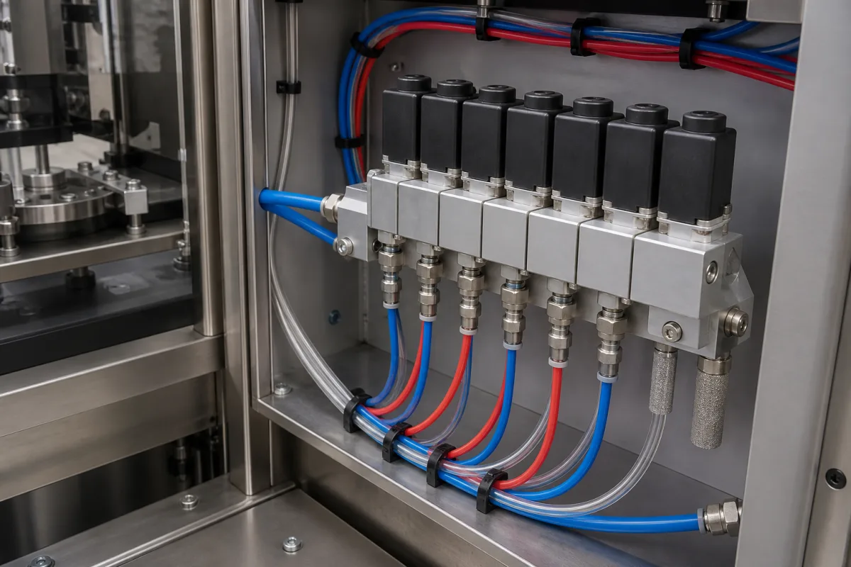
Representative product image. Confirm appearance and specifications with the manufacturer.

Product Specifications

Technical details and manufacturing context for Control Valve Manifold

Definition
The Control Valve Manifold is a critical component of the Leak Testing Module. It consolidates multiple control valves into a single manifold block, enabling precise routing, isolation, and regulation of test media (air, gas, or liquid) to and from the test specimen during leak detection procedures. This component is designed for use in machinery and equipment manufacturing, particularly in automated leak testing systems where reliable and repeatable flow control is essential. The manifold is typically constructed from stainless steel (e.g., 316L) or aluminum alloy, with PTFE seals and gaskets for compatibility with various test media. It features multiple ports (configurable from 2 to 8) with port sizes ranging from 1/4 to 1 inch (NPT or BSP threads). The operating pressure range is 1.0–1.6 MPa, with a note that The flow coefficient (Cv) ranges from 0.2 to 5.0, allowing for faster filling when higher Cv values are selected. The leakage rate is ≤0.01 sccm at rated pressure, ensuring minimal media loss. Response time is ≤50 ms from signal to full open, and the operating temperature range is -20 to 80°C, with seals degrading above 80°C. Electrical specifications include a 24 V DC supply (±10%) for solenoid pilot valves, with power consumption ≤8 W per solenoid. The electrical connection is a 4-pin M12×1 connector per IEC 61076-2-101. Ingress protection ranges from IP54 to IP65, with IP65 suitable for washdown environments. The body material is 316L stainless steel (ASTM A276) for corrosion resistance, and seal material is FKM (ASTM D2000) for compatibility with test media. Weight varies from 1.5 to 4.5 kg depending on port count. This component is a directory reference; model-specific values and standards must be verified with the legal manufacturer or supplier before procurement or use.
Working Principle
The Control Valve Manifold operates by using individual solenoid or pneumatic valves mounted on a common manifold body. A central controller actuates specific valves to open or close flow paths, directing the test medium through the system for pressurization, stabilization, and measurement phases of the leak test cycle. The manifold design consolidates multiple valves into a single block, reducing potential leak points and simplifying plumbing. Each valve is independently controlled, allowing for precise routing of media to different test circuits. The central controller sequences the valve operations based on the test program, ensuring that the correct flow paths are established at each phase. This enables accurate control of pressure, flow, and timing, which are critical for reliable leak detection results.
Common Materials
Stainless Steel (e.g., 316L), Aluminum Alloy, PTFE (Seals/Gaskets)
Technical Parameters
ParameterTypical rangeNotes & selection driver
Operating Pressure1.0–1.6 MPa
Port Size1/4–1 inchNPT or BSP threads
Number of Ports2–8Configurable for test circuits
Flow Coefficient (Cv)0.2–5.0 CvHigher Cv for faster filling
Leakage Rate≤0.01 sccmAt rated pressureISO 27895
Response Time≤50 msFrom signal to full open
Operating Temperature-20–80 °CSeals degrade above 80°C
Voltage24 ±10% V DCFor solenoid pilot valves
Power Consumption≤8 WPer solenoid
Electrical ConnectionM12×14-pin connectorIEC 61076-2-101
Ingress ProtectionIP54–IP65IP65 for washdownIEC 60529
Body Material316LCorrosion resistantASTM A276
Seal MaterialFKMCompatible with test mediaASTM D2000
Weight1.5–4.5 kgDepends on port count

Ranges are indicative industry figures for RFQ preparation, not a supplier commitment. Confirm every value and standard with the legal manufacturer before ordering.

Components / BOM
  • Manifold Body
    Primary block with machined fluid passages that interconnects all valves and ports
    Material: Stainless Steel or Aluminum
  • Solenoid Valve Cartridge
    Electrically actuated valve that opens/closes specific flow paths based on control signals
    Material: Stainless Steel, Brass, PTFE
  • Port Fittings Part
    Threaded or quick-connect fittings for attaching test lines and instrumentation
    Material: Stainless Steel, Brass

Applied To / Applications

This component is essential for the following industrial systems and equipment:

Industrial Ecosystem & Supply Chain Structure

Complementary Systems
Downstream Applications
Specialized Tooling

Application Fit & Sizing Matrix

Operational Limits
pressure: 0 to 100 bar (g)
flow rate: Up to 500 L/min
temperature: -20°C to 150°C
slurry concentration: Max 10% solids by weight
Media Compatibility
✓ Hydraulic oil (ISO VG 32-68) ✓ Compressed air (dry, filtered) ✓ Water/glycol mixtures
Unsuitable: Chlorinated solvents or strong acids
Sizing Data Required
  • Maximum system pressure (bar)
  • Required flow rate (L/min)
  • Number of test ports needed

Reliability & Engineering Risk Analysis

Failure Mode & Root Cause
Sticking or binding
Cause: Accumulation of process media deposits, corrosion products, or foreign particles in the valve trim or stem guide, often due to improper material selection, inadequate filtration, or infrequent maintenance cycles.
Internal leakage
Cause: Wear or damage to the valve seat and plug from cavitation, erosion (especially from high-velocity or abrasive fluids), or corrosion, potentially exacerbated by improper actuator sizing leading to insufficient seating force.
Maintenance Indicators
  • Erratic or unstable process control (e.g., hunting, oscillations in flow/pressure) indicating sticking, hysteresis, or internal component wear.
  • Visible external leakage from the valve stem packing or manifold connections, or audible hissing indicating seat leakage or gasket failure.
Engineering Tips
  • Implement a proactive maintenance program including regular stroking and partial-stroke testing to prevent sticking and verify performance, combined with periodic inspection and cleaning of trim components.
  • Ensure proper sizing and selection of valve trim materials (e.g., hardened alloys for erosive services, anti-cavitation trim) and install upstream strainers/filters to protect against particulate ingress, reducing wear and corrosion.

Indicative industry ranges for design and RFQ preparation. Confirm the exact figures and applicable standard with the manufacturer before specifying.

Compliance & Manufacturing Standards

Applicable Standards
ISO 15848-1:2015 (Leakage classification and testing of valve assemblies) ANSI/ISA 75.08.01-2002 (Face-to-face dimensions for flanged control valves) DIN EN 1092-1 (Flanges and their joints - Circular flanges for pipes, valves, fittings and accessories)

Quoted from the published standard.

Manufacturing Precision
  • Bore diameter: +/-0.025mm
  • Flange flatness: 0.1mm per 300mm diameter
Quality Inspection
  • Hydrostatic pressure test (per API 598)
  • Dye penetrant test for surface defects

Manufacturers of Control Valve Manifold

Manufacturer profiles associated with Control Valve Manifold.

Sourcing Control Valve Manifold from China?
Tell us your specification and target quantity — we will match it against manufacturer records and come back with the factories that fit.
Request manufacturers We manufacture this

Manufacturer listings support early research and capability understanding. They are not certification, ranking, or transaction guarantees.

Technical documentation
Request current drawings, revision history, and a signed specification sheet.
Manufacturing capability
Verify equipment lists, process limits, capacity, and representative production evidence.
Inspection readiness
Confirm test methods, calibrated equipment, sampling plans, and traceable reports.
Supplier transparency
Check the legal entity, factory address, ownership, certifications, and direct contacts.

CNFX does not score or rank suppliers. Buyers must verify all claims and documents with the legal manufacturer before ordering.

Supply Chain Compatible Machinery & Devices

Hydraulic Press

Industrial machine using hydraulic pressure to compress, form, or assemble materials

Explore Specs →
Heavy-Duty CNC Plasma Cutting Machine

The Heavy-Duty CNC Plasma Cutting Machine is a standalone industrial device designed for cutting conductive metals such as steel, stainless steel, aluminum, and copper alloys.

Explore Specs →
Automated Powder Coating System

Integrated industrial system for applying dry powder coatings to metal substrates.

Explore Specs →
Centrifugal Pump Impeller

The centrifugal pump impeller is a critical rotating component that converts mechanical energy from the motor into kinetic energy in fluid systems.

Explore Specs →

Frequently Asked Questions

What is the operating pressure range of the Control Valve Manifold?

The operating pressure range is 1.0–1.6 MPa.

What materials are used for the manifold body and seals?

The body is typically made of stainless steel (e.g., 316L) or aluminum alloy. Seals and gaskets are made of PTFE. The seal material is also specified as FKM (ASTM D2000) for compatibility with test media.

What is the leakage rate of the manifold?

The leakage rate is ≤0.01 sccm at rated pressure, as per ISO 27895. This ensures minimal media loss during leak testing.

What electrical connection does the manifold use?

The electrical connection is a 4-pin M12×1 connector, conforming to IEC 61076-2-101. The voltage is 24 V DC (±10%) for solenoid pilot valves, with power consumption ≤8 W per solenoid.

Data Basis

Editorial classification, named public sources where available, and source-reviewed manufacturer records.

Preliminary Technical Classification
This page supports structured research, RFQ preparation, and supplier evaluation. It does not replace buyer-led supplier qualification, standards review, or technical approval.
Buyer enquiry

Request manufacturing insight for Control Valve Manifold

Ask for use case, specification boundaries, supplier type, and RFQ preparation information for this product.

Where it goes
Straight to the CNFX editorial desk, and to the manufacturer if this product is linked to a claimed profile. Nothing is broadcast to a supplier list.
Your details stay here
We do not sell or rent enquiry data, and we do not add you to a mailing list. Used only to answer this request.
No commission, no middleman
CNFX is a directory. We take no cut of any order and never negotiate on a supplier's behalf.
What we don't claim
A listing is not an endorsement. Qualify every supplier and verify every figure yourself before ordering.

Your business information is used only to process this request.

Thank you! Your message has been sent. We'll respond within 1–3 business days.
Sorry, we couldn't send your message. Please try again, or email us at contact@cnfx.com.

Need to Manufacture Control Valve Manifold?

Compare manufacturer profiles with relevant product and process capability.

Previous Product
Z-axis Ram/Spindle
Last Product
Get QuotesChat