Editorial Technical Reference

Injection Nozzles

This page explains how Injection Nozzles is classified within Chemical Manufacturing. Technical values and manufacturer relationships are research references; confirm the current specification and supplier evidence for each order.

Technical Definition & Core Assembly

Precision components designed to accurately dispense and atomize chemical additives into a process stream within a dosing system.
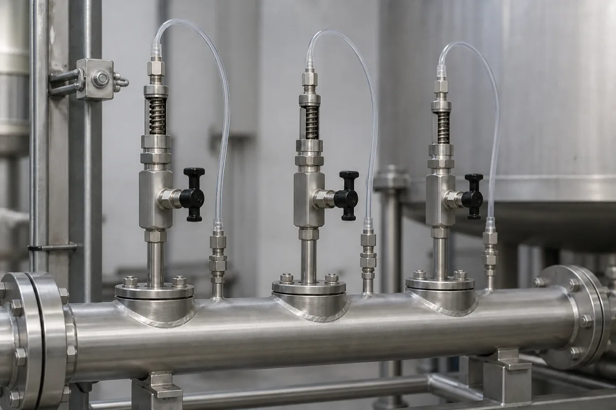
Representative product image. Confirm appearance and specifications with the manufacturer.

Product Specifications

Technical details and manufacturing context for Injection Nozzles

Definition
Injection nozzles are critical components of chemical dosing systems that precisely control the introduction of liquid or gaseous chemicals into industrial processes. They ensure accurate flow rates, proper atomization for mixing, and controlled spray patterns to achieve uniform chemical distribution. These nozzles are engineered to handle various chemical properties, pressures, and temperatures while maintaining dosing accuracy and reliability.

In a typical dosing system, the nozzle is installed at the point of injection, where it converts the pressurized chemical flow into a fine spray or stream. The internal geometry of the nozzle, including precisely machined orifices and flow channels, determines the spray characteristics. As the chemical passes through, it accelerates and atomizes into droplets of a specific size range, which is critical for efficient mixing and reaction. The nozzle's design also controls the spray angle and flow rate, which must match the process requirements.

Selection of an injection nozzle involves specifying the operating pressure, flow rate, spray angle, droplet size, connection size, and material of construction. The material must be compatible with the chemical being handled, considering corrosion resistance and temperature limits. For example, stainless steel 316L is commonly used for general chemical service, while Hastelloy C-276 is suited for more aggressive media. PTFE and ceramic options are available for specialized applications.

Verification of nozzle performance should include checking the flow rate at the specified pressure, measuring the spray pattern and droplet size, and confirming the sealing class. The operating pressure range is typically 1.0–1.6 MPa. The flow rate ranges from 0.5 to 5.0 L/min, depending on nozzle size and pressure. The spray angle can vary from 30 to 120 degrees, affecting coverage and atomization. Droplet size (Sauter mean) is typically 50–500 µm, which is critical for chemical reaction efficiency. Connection sizes are standard pipe threads from 1/8 to 1 inch per ISO 7-1. The maximum operating temperature is 200°C, above which material degradation occurs. Weight ranges from 0.05 to 0.5 kg. Precision (flow tolerance) is ±5%, ensuring dosing accuracy. Sealing class is VI.

Always verify model-specific values and standards with the legal manufacturer or supplier before procurement.
Working Principle
Injection nozzles operate by converting pressurized chemical flow into a controlled spray pattern through precisely engineered orifices and internal geometries. As the chemical passes through the nozzle, it undergoes acceleration and atomization, breaking into fine droplets or streams for optimal dispersion into the target medium. The design controls flow rate, spray angle, droplet size, and distribution pattern based on the specific application requirements.
Common Materials
Stainless Steel 316L, Hastelloy C-276, PTFE (Polytetrafluoroethylene), Ceramic
Technical Parameters
ParameterTypical rangeNotes & selection driver
Flow Rate0.5–5.0 L/minDepends on nozzle size and pressure
Spray Angle30–120 °Affects coverage and atomization
Droplet Size (Sauter Mean)50–500 µmCritical for chemical reaction efficiency
Connection Size1/8–1 inchStandard pipe thread sizesISO 7-1
Material Grade316LCorrosion resistance for chemical serviceASTM A276
Maximum Operating Temperature200 °CAbove this, material degradation occurs
Weight0.05–0.5 kgVaries with size and material
Precision (Flow Tolerance)±5 %Ensures dosing accuracy
Sealing ClassVILeakage rate per ISO 5208

Ranges are indicative industry figures for RFQ preparation, not a supplier commitment. Confirm every value and standard with the legal manufacturer before ordering.

Components / BOM
  • Nozzle Body
    Main structural component housing internal flow channels and providing connection points
    Material: Stainless Steel
  • Orifice Plate/Insert Part
    Precision component with calibrated opening that controls flow characteristics
    Material: Hardened Steel or Ceramic
  • Swirl Chamber Part
    Internal geometry that imparts rotational motion to fluid for atomization
    Material: Stainless Steel
  • Sealing Gasket/O-ring Part
    Ensures leak-proof connection between nozzle and mounting fixture
    Material: Viton or PTFE
  • Spray Tip Part
    Final exit point that shapes and directs the spray pattern
    Material: Wear-resistant Alloy

Applied To / Applications

This component is essential for the following industrial systems and equipment:

Industrial Ecosystem & Supply Chain Structure

Complementary Systems
Downstream Applications
Specialized Tooling

Application Fit & Sizing Matrix

Operational Limits
pressure: Up to 100 bar
flow rate: 0.1 to 50 L/min
temperature: -20°C to 150°C
slurry concentration: Up to 30% solids by weight
Media Compatibility
✓ Water-based chemical additives ✓ Polymer solutions ✓ Corrosion inhibitors
Unsuitable: Highly abrasive slurries with >30% solids or corrosive media exceeding pH 12
Sizing Data Required
  • Required flow rate (L/min)
  • Process stream pressure (bar)
  • Additive viscosity (cP)

Reliability & Engineering Risk Analysis

Failure Mode & Root Cause
Abrasive erosion
Cause: High-velocity flow of abrasive particles in the fluid eroding the nozzle orifice and internal surfaces, often due to contaminated fluids or inadequate filtration.
Thermal fatigue cracking
Cause: Repeated thermal cycling from rapid heating and cooling during operation, leading to stress cracks, typically from improper temperature control or material incompatibility.
Maintenance Indicators
  • Irregular spray pattern or visible dripping from the nozzle tip during operation
  • Unusual whistling or hissing sounds indicating flow restriction or internal damage
Engineering Tips
  • Implement a multi-stage filtration system upstream to remove particles larger than 10% of the nozzle orifice diameter
  • Use thermal barrier coatings on nozzle surfaces and maintain consistent operating temperatures within material specifications

Indicative industry ranges for design and RFQ preparation. Confirm the exact figures and applicable standard with the manufacturer before specifying.

Compliance & Manufacturing Standards

Applicable Standards
ISO 294-1:2017 (Plastics - Injection moulding of test specimens) ASTM D3641-15 (Standard Practice for Injection Molding Test Specimens of Thermoplastic Molding and Extrusion Materials) DIN 16742 (Plastics - Moulded parts - Tolerances and acceptance conditions for thermoplastics mouldings)

Quoted from the published standard.

Manufacturing Precision
  • Nozzle orifice diameter: +/-0.01mm
  • Seating surface flatness: 0.02mm
Quality Inspection
  • Dimensional verification with coordinate measuring machine (CMM)
  • Pressure decay leak test

Manufacturers of Injection Nozzles

Manufacturer profiles associated with Injection Nozzles.

Sourcing Injection Nozzles from China?
Tell us your specification and target quantity — we will match it against manufacturer records and come back with the factories that fit.
Request manufacturers We manufacture this

Manufacturer listings support early research and capability understanding. They are not certification, ranking, or transaction guarantees.

Technical documentation
Request current drawings, revision history, and a signed specification sheet.
Manufacturing capability
Verify equipment lists, process limits, capacity, and representative production evidence.
Inspection readiness
Confirm test methods, calibrated equipment, sampling plans, and traceable reports.
Supplier transparency
Check the legal entity, factory address, ownership, certifications, and direct contacts.

CNFX does not score or rank suppliers. Buyers must verify all claims and documents with the legal manufacturer before ordering.

Supply Chain Compatible Machinery & Devices

Automated Batch Crystallization System

Automated system for controlled crystallization of chemical compounds in batch processes.

Explore Specs →
Automated pH Monitoring and Dosing System

Automated system for continuous pH monitoring and chemical dosing in process streams.

Explore Specs →
Automated Powder Dispensing and Blending System

Automated system for precise dispensing and homogeneous blending of powdered chemicals.

Explore Specs →
Automated Viscosity Control and Mixing System

The Automated Viscosity Control and Mixing System is an industrial automation solution designed for continuous monitoring and adjustment of viscosity in chemical mixing and blending operations.

Explore Specs →

Frequently Asked Questions

What are the typical operating pressure and flow rate ranges for injection nozzles?

The operating pressure range is 1.0–1.6 MPa. The flow rate ranges from 0.5 to 5.0 L/min, depending on nozzle size and pressure. These values are reference ranges; actual performance must be confirmed for the specific model and application.

What materials are available for injection nozzles?

Common materials include Stainless Steel 316L, Hastelloy C-276, PTFE, and Ceramic. The material grade listed is 316L per ASTM A276. Material selection depends on chemical compatibility, temperature, and corrosion resistance requirements.

What standards apply to injection nozzles?

Relevant standards include, ISO 7-1 for pipe threads, and ASTM A276 for stainless steel material grade. These standards serve as procurement references; compliance must be verified with the manufacturer.

How do I verify the performance of an injection nozzle?

Verify flow rate at the specified pressure, measure spray angle and droplet size, and check the sealing class. Also confirm the connection size and material grade. Always consult the manufacturer for model-specific data and ensure the nozzle meets your process requirements.

Data Basis

Editorial classification, named public sources where available, and source-reviewed manufacturer records.

Preliminary Technical Classification
This page supports structured research, RFQ preparation, and supplier evaluation. It does not replace buyer-led supplier qualification, standards review, or technical approval.
Buyer enquiry

Request manufacturing insight for Injection Nozzles

Ask for use case, specification boundaries, supplier type, and RFQ preparation information for this product.

Where it goes
Straight to the CNFX editorial desk, and to the manufacturer if this product is linked to a claimed profile. Nothing is broadcast to a supplier list.
Your details stay here
We do not sell or rent enquiry data, and we do not add you to a mailing list. Used only to answer this request.
No commission, no middleman
CNFX is a directory. We take no cut of any order and never negotiate on a supplier's behalf.
What we don't claim
A listing is not an endorsement. Qualify every supplier and verify every figure yourself before ordering.

Your business information is used only to process this request.

Thank you! Your message has been sent. We'll respond within 1–3 business days.
Sorry, we couldn't send your message. Please try again, or email us at contact@cnfx.com.

Need to Manufacture Injection Nozzles?

Compare manufacturer profiles with relevant product and process capability.

Previous Product
Twin-Screw Polymer Compounding Extruder
Last Product
Get QuotesChat