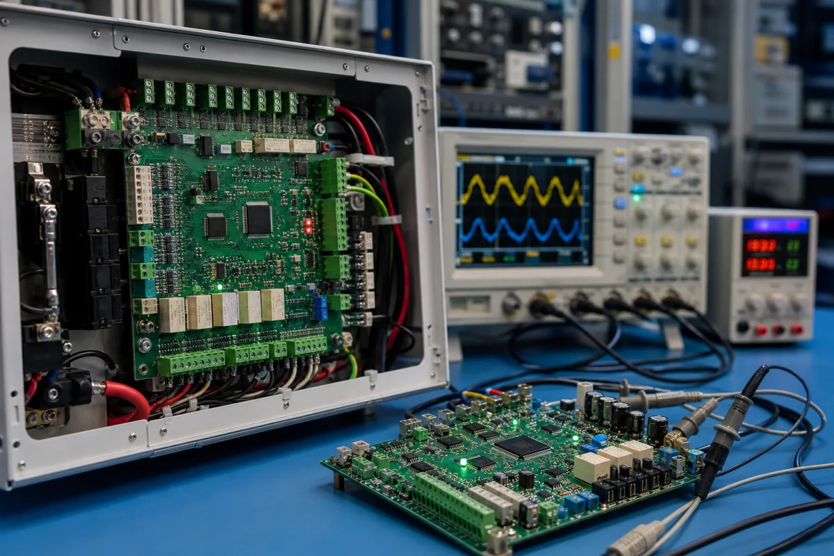
Control and monitoring I/O board with relays, isolated inputs and RS-485
Equipment I/O boards · relay and MOSFET outputs, isolated digital and 4–20 mA inputs, 0–10 V I/O, RS-485/Modbus, protection
A control and monitoring board is a finished circuit board, sold as a product, that carries the inputs and outputs a machine or panel needs, such as relays, transistor outputs, isolated digital inputs and 0–10 V or 4–20 mA analog channels, together with a microcontroller and a bus such as RS-485/Modbus so that a PLC, PC or single-board computer can command it. Ask three things first: what each output must switch (voltage, current, load type), what each input must read and how it is isolated, and which bus, protocol and addressing the board uses.
Off-the-shelf and configurable control and monitoring I/O boards and relay boards for machines, panels and building or process equipment, with their I/O, isolation, protection and communication. Contract PCB assembly (PCBA) services that build boards to a customer's own design are covered on the PCB assembly (PCBA) service page. Battery management boards, PLCs and complete control panels are outside this page.
CNFX editorial research · Sources checked October 12, 2026 · 4 sources
Waveshare's Modbus RTU Relay board has eight relays with 1NO/1NC contacts rated at up to 10 A 250 VAC or 30 VDC, in a DIN-rail ABS enclosure; its range runs from 4 to 32 channels, with 20 A high-current and latching-relay versions, 5 V or 7–36 V supply, and sizes from 145 × 90 × 40 mm to 300 × 110 × 60 mm. [1]
Sequent Microsystems' eight-relay card for Raspberry Pi rates its NO/NC contacts at 4 A at 120 VAC or 24 VDC, with a status LED per relay, while its industrial automation card uses four 4 A/24 V MOSFET outputs and four open-drain PWM outputs instead of relays. [4][3] Editorial calculation: at 24 VDC, a 4 A contact can switch about 96 W of resistive load and a 10 A contact at 30 VDC about 300 W; these are contact ratings, not motor or lamp ratings.
Waveshare's own safety notes warn that inductive loads such as motors, coils and lamps can draw starting currents well above their rated current, recommend fusing each relay circuit, and recommend RC snubbers or varistors to suppress switching arcs. [2] Editorial note: list the inrush current and load type for each output, and ask the supplier for the relay's rated life at your load.
Give the supplier each output's load type, voltage and running and inrush current; each input's signal (dry contact, 24 V, 0–10 V, 4–20 mA, temperature); isolation required; bus and protocol; supply voltage; mounting (DIN rail, panel, stacked on a host); connector type; and the operating temperature.
02
Isolate and scale the inputs
Sequent Microsystems' industrial automation card lists four optically isolated digital inputs, four optically isolated 4–20 mA inputs for 2-, 3- or 4-wire transmitters, four 16-bit 0–10 V or ±10 V analog inputs, four 14-bit 0–10 V outputs and four 14-bit 4–20 mA outputs with load-interruption detection. It samples the 0–10 V inputs at 215 Hz and the 4–20 mA inputs at 675 Hz, protects all inputs with TVS diodes, and adds a hardware watchdog, fuse and battery-backed real-time clock. [3]
Waveshare describes its relay board as having onboard power isolation, magnetic signal isolation, a resettable fuse and TVS diodes against surges and transient spikes. [1] Editorial calculation: a 16-bit 0–10 V input resolves 10 V ÷ 65,536 ≈ 0.15 mV per count, and a 14-bit 4–20 mA output steps 16 mA ÷ 16,384 ≈ 1 µA; ask for accuracy as well, since resolution alone does not state it.
Editorial note: ask which channels share a ground reference, what isolation voltage is tested between field side and logic side, and whether the supplier can show the test record.
03
Set the bus, protocol and addressing
Waveshare's relay board speaks standard Modbus RTU over RS-485 at 4,800 to 256,000 baud, defaults to 9600 baud with 8 data bits, no parity and 1 stop bit, and takes an address from 1 to 255 so that more than one board can be cascaded on one bus; it notes that RS-485 repeaters are needed when the bus is long or carries a large number of devices. [1]
Sequent's cards talk to a Raspberry Pi over I2C, stack up to eight levels, and also provide an RS-485/Modbus port so a card can run as a standalone module under a PLC; they list Python, Node-RED, CODESYS and OpenPLC support. [4][3] Waveshare also offers versions with Ethernet and PoE. [1]
04
I/O ratings, isolation, protocol documentation and supply range to request per board
Ask each supplier for the I/O table with ratings, isolation and protection details, bus and protocol documentation, supply range, enclosure or mounting, and the operating temperature range.
05
Microcontroller, relay outputs, isolated inputs, analog I/O, RS-485 transceiver and protection
Explore company information and manufacturing capabilities, then discuss the scope of your project with a relevant supplier.
Share this page
Compiled and source-reviewed by the CNFX editorial team.
Each manufacturer above links to the page on that company's own website where the product is listed, with the date we checked it. How we source and review
· Page last updated 13 October 2026
Buyer questions
What contact rating do relay I/O boards list?
Waveshare's Modbus RTU relay board lists up to 10 A at 250 VAC or 30 VDC; Sequent's relay card lists 4 A at 120 VAC or 24 VDC. [1][4]
Can one board read 4–20 mA sensors and drive 0–10 V outputs?
Sequent's industrial automation card lists four isolated 4–20 mA inputs, four 16-bit 0–10 V inputs and 14-bit 0–10 V and 4–20 mA outputs. [3]
How many boards can share one RS-485 bus?
Waveshare's relay board takes addresses 1–255 and notes that repeaters are needed for long buses or large device counts. [1]
Sources and what still needs a direct check
Sources checked 2026-10-12. Waveshare and Sequent Microsystems are board makers describing their own products. Figures are for the boards named and must be confirmed for the unit you buy.