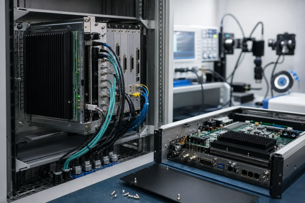
MicroTCA.4 signal-processing control unit: FPGA digitizer cards and rear transition modules that close fast analogue feedback loops
Crate-based real-time signal processing for fast feedback control · MicroTCA.4 digitizer and FPGA cards, rear transition modules that condition analogue signals, and what such a unit achieves when it regulates accelerator RF fields
Some control loops are too fast and too precise for a PLC or a microcontroller board. Regulating the radio-frequency field in an accelerator cavity, reading beam monitors or driving a fast actuator needs ten or more analogue channels digitised at tens of megasamples per second and a feedback algorithm that answers within the same pulse. One way of building that control unit is a MicroTCA.4 crate: digitizer cards with an FPGA at the front, analogue signal conditioning on rear transition modules behind them, and a CPU card and carrier hub that handle the slower supervisory work.
Crate-based real-time signal-processing control units on the MicroTCA.4 platform: advanced mezzanine card (AMC) digitizers and FPGA controller cards with feedback DACs, rear transition modules (RTMs) for analogue signal conditioning, down-conversion and vector modulation, the MicroTCA carrier hub, power modules, CPU card and management, as used for accelerator low-level RF control, beam diagnostics and similar fast feedback loops. Microcontroller and embedded processor chips are covered on the Microcontrollers (CPU / MCU) page; product-specific MCU control boards for appliances and machines on the Main control board for an appliance or machine page; EN 50155 rolling-stock computers on the Rolling-stock processing module page; multi-camera vision controllers on the Vision processing unit page; low-power MCUs for data loggers on the Low-power microcontroller (MCU) for battery-powered data loggers page; audio analogue-to-digital converters on the Analog-to-digital converter for audio page. DSP and FPGA devices as individual chips are outside this page.
CNFX editorial research · Sources checked October 12, 2026 · 4 sources
Where the work sits in a MicroTCA.4 crate: FPGA digitizers in front, analogue conditioning behind, CPU for the slow tasks
PICMG, which publishes the MicroTCA specifications, describes the minimum system as at least one advanced mezzanine card (AMC), one MicroTCA Carrier Hub (MCH) and the interconnect, power, cooling and mechanics around them. A typical system supports up to twelve AMCs, with optional redundant MCHs, power modules and cooling; a single MCH can manage up to twelve AMCs. Rear transition modules (RTMs) are optional and add connectivity the AMC front panel cannot carry. Backplane data links are differential SerDes lanes of at least 3.125 Gbps in each direction, carrying PCI Express, Ethernet or RapidIO, and IPMI-based management handles monitoring and failure isolation. [1]
Kay Rehlich of DESY, describing the laboratory's choice of the platform for the European XFEL, dates MicroTCA.0 to 2006, MicroTCA.4 to 2011 and MicroTCA.4.1 to 2016. DESY's early evaluation from 2008 with single MTCA.0 modules, including an in-house AMC with a Virtex 5 FPGA and two 100 MSPS ADCs, concluded that single modules were too small, left no space for signal conditioning and forced cables in from the front, and DESY started a PICMG group to extend the standard. [2]
The resulting MTCA.4 crate provides rear cable entry onto RTMs, with redundant fans and one to four power supplies. Rehlich's division of labour is the point of the architecture: complex work runs on a standard CPU for faster development, while real-time processing runs in the FPGA so that the CPU software can crash without disturbing accelerator operation; clocks, triggers and interlocks are distributed through the crate, and remote management is described as a must for large facilities. [2]
Crate element
Role in the control unit
AMC digitizer or controller card
Digitises signals and runs the real-time algorithm in an FPGA [2][3]
Rear transition module (RTM)
Analogue signal conditioning, amplification or down-conversion behind the AMC [2][3]
MicroTCA Carrier Hub (MCH)
Manages up to twelve AMCs and controls data flow; may include the fabric switch [1]
CPU card
Control-system interface and supervisory software, linked to FPGAs over PCIe [2]
Power modules
Convert and distribute power, with redundancy and load sharing options [1]
Backplane
SerDes links of at least 3.125 Gbps each way; star, dual-star or mesh topologies [1]
Specify how many analogue channels, at what bandwidth, must be read per crate, which functions must keep running if the CPU stops, and whether clock, trigger and interlock signals are distributed on the backplane or by cable.
02
The digitizer card: ten 16-bit channels at 125 MS/s, a Kintex UltraScale FPGA and two feedback DACs
Struck Innovative Systeme's SIS8300-KU is an MTCA.4 digitizer with 10 channels of 16-bit ADC at 125 MS/s, per-channel sampling speed selectable from 10 to 125 MS/s, and two 16-bit DACs for fast feedback. Struck states that the SIS8300 family was developed in co-operation with DESY; the KU is the Kintex UltraScale successor to the SIS8300-L2. [3]
The card uses an XCKU040 Kintex UltraScale FPGA with 2 GB of DDR4 memory, a 4-lane PCI Express Gen3 link, a Gigabit link port to the backplane and a twin SFP+ cage for fast interconnects, and takes its clock from internal, front-panel, RTM or backplane sources. It ships with ready-to-run firmware and Xilinx Vivado projects so the firmware can be adapted, and White Rabbit is offered for sub-nanosecond timing. [3] DESY lists a 10-channel, 16-bit, 125 MSPS commercial ADC of this type, the SIS8300, as the digitizer behind toroid protection, the readout of kickers and other devices (listed on the slide as “Kicker, FC, etc.”) and the LLRF controller at the European XFEL. [2]
Editorial calculation, assuming each 16-bit sample is stored as 2 bytes: 10 channels at 125 MS/s produce 2.5 GB of raw samples per second, so the card's 2 GB of DDR4 would hold about 0.8 s of continuous data from all channels; at the 10 MS/s minimum rate the same memory holds about 10 s. [3]
Struck lists RTMs for the SIS8300 family including a single-ended input card, a 10-channel downconverter, an 8-channel downconverter with one vector modulator and an 8-channel direct-sampling card with one vector modulator; ask which RTM and Zone 3 class the AMC is matched to.
03
What the unit achieves in a fast loop: European XFEL cavity fields held to 0.008% and 0.007° rms
A 2013 IPAC paper by DESY and partner institutes describes the European XFEL low-level RF (LLRF) system built on MTCA.4: more than 800 superconducting cavities driven by 25 multi-beam klystrons, more than 3,000 RF channels to process, and a requirement for field stability better than 0.01° in phase and 0.01% in amplitude. [4]
Each RF station spans 50 m with four cryomodules of eight 1 m cavities, and its signals are processed in two MTCA.4 crates, a master and a slave, linked by a direct optical connection; each crate sums a partial vector of 16 cavities, the master forms the global vector sum and its MIMO feedback controller, iterative learning feed-forward and beam-loading compensation generate the klystron drive at 1.3 GHz. [4]
At FLASH, controlling one cryomodule in closed loop, the paper reports amplitude and phase regulation over the RF flattop of 0.008% and 0.007° rms, and single-channel measurement accuracy improved to 0.003% in amplitude and 3 mdeg in phase. Inside shielded LLRF racks it measured 0.45 mGy/h and an average of 2 single-event upsets per hour, with no detected influence on CPU and memory and the effect on FPGA code still to be investigated. It notes that FEL experiments were asking for 0.001% and 1 mdeg. [4]
The paper also names the RTM functions behind those figures: down-converters, vector modulators and a combined module (uDWC-VM) paired with the SIS8300L digitizer for single-cavity control, an RF backplane distributing reference, local oscillator and clock to the rear modules, and a local-oscillator generation module. [4]
0.45 mGy/h; about 2 single-event upsets per hour [4]
For a fast feedback application, state the loop's required amplitude and phase (or value) stability, the number of channels per crate, the operating frequency and any down-conversion needed, and the radiation or electrical environment of the rack.
04
Channel, loop and crate data for a signal-processing control unit
Paste it into your enquiry below or into an email to a maker, then replace every bracket.
Signals: [number of analogue channels; frequency or bandwidth; AC or DC coupling; levels]
Sampling: [MS/s per channel; resolution]
Conditioning: [RTM type: amplifier, down-converter, vector modulator, direct sampling]
Loop: [required stability or accuracy; latency; feedback DAC outputs]
FPGA and firmware: [supplied firmware or customer firmware; tool chain]
Crate: [number of AMC slots; MCH; CPU card; redundant power and cooling]
Timing: [clock source; trigger and interlock distribution; White Rabbit]
Environment: [rack location; radiation; remote management]
Explore company information and manufacturing capabilities, then discuss the scope of your project with a relevant supplier.
Share this page
Compiled and source-reviewed by the CNFX editorial team.
Each manufacturer above links to the page on that company's own website where the product is listed, with the date we checked it. How we source and review
· Page last updated 13 October 2026
Buyer questions
What is a rear transition module in MicroTCA.4?
PICMG describes an RTM as an optional module adding connectivity the AMC front panel cannot carry; DESY uses RTMs for analogue signal conditioning and down-conversion behind the digitizer cards. [1][2]
How fast does a MicroTCA.4 digitizer sample?
Struck's SIS8300-KU samples 10 channels at 16 bit and up to 125 MS/s, selectable down to 10 MS/s, with two 16-bit feedback DACs and a Kintex UltraScale FPGA. [3]
Why put real-time control in the FPGA instead of the CPU?
DESY's rationale is that the CPU handles complex, non-real-time work while the FPGA runs the real-time loop, so CPU software can crash without disturbing accelerator operation. [2]
How precise is MTCA.4-based RF field control?
At FLASH one cryomodule was regulated to 0.008% in amplitude and 0.007° in phase rms, against a European XFEL requirement of better than 0.01% and 0.01°. [4]
Sources and what still needs a direct check
Sources checked 2026-10-12. PICMG publishes the MicroTCA specifications; DESY is the laboratory that drove the MTCA.4 extension and runs it at the European XFEL, described here in a 2021 workshop talk and a 2013 IPAC paper; Struck Innovative Systeme makes the digitizer card whose figures are quoted.