Editorial Technical Reference

Precision Stacking Stage

This page explains how Precision Stacking Stage is classified within Computer, Electronic and Optical Product Manufacturing. Technical values and manufacturer relationships are research references; confirm the current specification and supplier evidence for each order.

Technical Definition & Core Assembly

A precision positioning and alignment component within an electrode stacking module that ensures accurate layer-by-layer assembly of electrode materials.
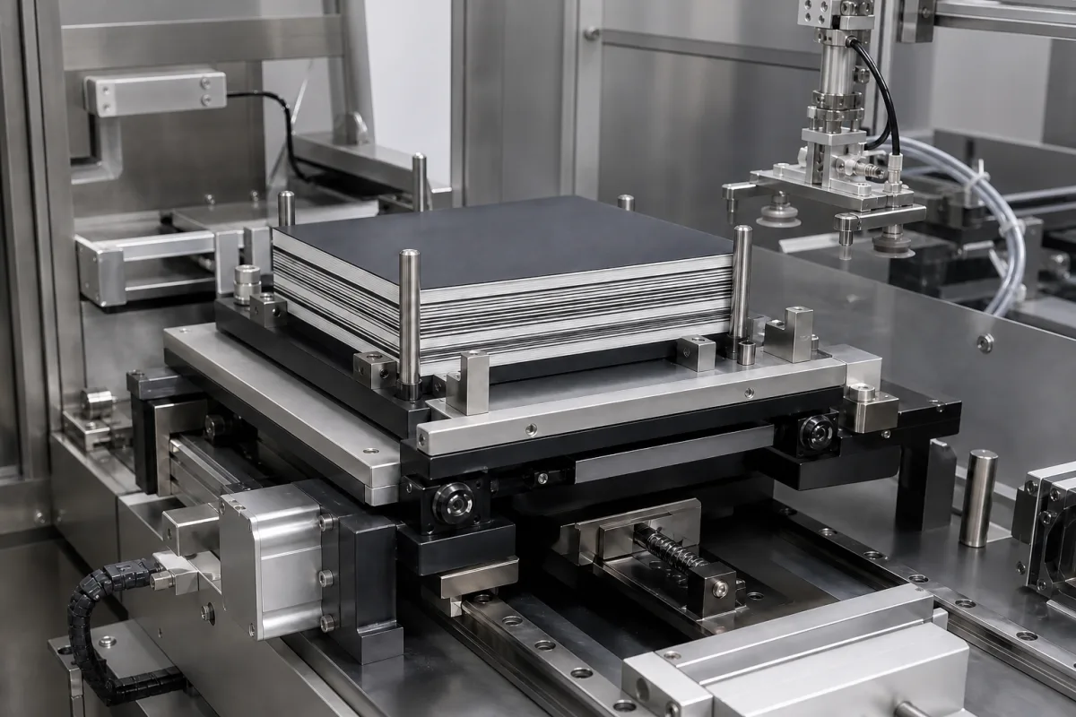
Representative product image. Confirm appearance and specifications with the manufacturer.

Product Specifications

Technical details and manufacturing context for Precision Stacking Stage

Definition
The Precision Stacking Stage is a critical sub-component of the Electrode Stacking Module in battery manufacturing systems. It provides the precise mechanical platform and motion control necessary for the accurate, repeatable placement and alignment of electrode layers (anodes, cathodes, separators) during the stacking process to form battery cells. Its primary role is to eliminate misalignment and ensure consistent layer registration, which is essential for battery performance, safety, and yield. The stage typically operates using high-precision linear guides or ball screws driven by servo motors. It receives positional commands from the system's control unit, moves the electrode materials or the stacking head to a programmed coordinate with micron-level accuracy, and holds position during the placement or lamination step. Feedback from encoders or laser sensors ensures the target position is achieved and maintained. The stage is designed for integration into automated battery production lines, where it interfaces with upstream and downstream equipment. It is available in configurations with positioning accuracy of ±0.01 mm (ISO 230-2), repeatability of ±0.005 mm (ISO 230-2), travel range of 200–400 mm, maximum load capacity of 50–100 kg, positioning speed of 100–300 mm/s, operating temperature of 15–35 °C, relative humidity of 45–65% RH, ingress protection of IP54–IP65 (IEC 60529), supply voltage of 24 V DC ±10%, power consumption of 50–150 W, and weight of 80–120 kg. The footprint ranges from 600×600 mm to 800×800 mm. Materials used include aluminum alloy (frame/body), stainless steel (guide rails/bearings), and ceramic or composite materials for thermal/electrical insulation where needed. The stage is a component, not a standalone machine, and its performance must be verified in the context of the specific stacking module and battery cell design. Buyers should confirm model-specific values and standards with the legal manufacturer or supplier, as the listed parameters are reference ranges for directory purposes.
Working Principle
The stage uses high-precision linear guides or ball screws driven by servo motors. It receives positional commands from the system's control unit, moves the electrode materials or the stacking head to a programmed coordinate with micron-level accuracy, and holds position during the placement or lamination step. Feedback from encoders or laser sensors ensures the target position is achieved and maintained.
Common Materials
Aluminum alloy (frame/body), Stainless steel (guide rails/bearings), Ceramic or composite materials (for thermal/electrical insulation where needed)
Technical Parameters
ParameterTypical rangeNotes & selection driver
Positioning Accuracy±0.01 mmCritical for layer alignmentISO 230-2
Repeatability±0.005 mmEnsures consistent stackingISO 230-2
Travel Range200–400 mmDepends on electrode size
Maximum Load Capacity50–100 kgIncludes fixture and stack weight
Positioning Speed100–300 mm/sHigher speed reduces cycle time
Operating Temperature15–35 °COutside range affects accuracy
Relative Humidity45–65 % RHHigh humidity may cause corrosion
Ingress ProtectionIP54–IP65Protects against dust and waterIEC 60529
Supply Voltage24 ±10% V DCStable voltage required
Power Consumption50–150 WIncludes motors and sensors
MaterialAluminum 6061Lightweight and corrosion-resistantASTM B209
Weight80–120 kgAffects installation and handling
Footprint600×600–800×800 mmSpace required for installation

Ranges are indicative industry figures for RFQ preparation, not a supplier commitment. Confirm every value and standard with the legal manufacturer before ordering.

Components / BOM
  • Linear Guide Rail
    Provides a low-friction, high-rigidity path for precise linear motion of the stage carriage.
    Material: Stainless steel or hardened steel
  • Carriage/Platform
    The moving platform that holds or positions the electrode materials or tooling during the stacking process.
    Material: Aluminum alloy or composite
  • Servo Motor
    Provides controlled rotational force to drive the ball screw or belt system for precise positioning.
    Material: Various (housing: aluminum, internals: copper windings, magnets)
  • Ball Screw or Lead Screw
    Converts the rotational motion of the servo motor into precise linear motion of the carriage.
    Material: Steel (often hardened and ground)
  • Linear Encoder
    Provides high-resolution feedback on the actual position of the carriage to the control system for closed-loop control.
    Material: Various (glass or steel scale, optical or magnetic reader head)

Applied To / Applications

This component is essential for the following industrial systems and equipment:

Industrial Ecosystem & Supply Chain Structure

Complementary Systems
Downstream Applications
Specialized Tooling

Application Fit & Sizing Matrix

Operational Limits
pressure: Max 0.5 MPa (5 bar) on stage surface
other spec: Positioning accuracy: ±2 μm, Repeatability: ±0.5 μm, Max load capacity: 50 kg, Vibration tolerance: <0.1 g RMS
temperature: 15°C to 35°C (operating), -10°C to 50°C (storage)
Media Compatibility
✓ Lithium-ion electrode slurry (NMC/LFP) ✓ Dry electrode films ✓ Separator membranes
Unsuitable: Corrosive chemical environments (acids, strong solvents)
Sizing Data Required
  • Maximum electrode sheet dimensions (width × length)
  • Required stacking speed (layers per minute)
  • Total stack height/thickness requirement

Reliability & Engineering Risk Analysis

Failure Mode & Root Cause
Misalignment-induced bearing failure
Cause: Incorrect installation, thermal expansion, or foundation settling causing shaft misalignment, leading to excessive radial loads and premature bearing wear.
Motor drive overload and overheating
Cause: Excessive stacking loads, frequent start-stop cycles, or voltage fluctuations causing thermal stress on windings and insulation breakdown.
Maintenance Indicators
  • Unusual high-pitched whining or grinding noise from drive components during operation
  • Visible vibration or wobble in the stacking mechanism during precision movements
Engineering Tips
  • Implement laser alignment checks quarterly and after any maintenance involving drive components to maintain optimal shaft alignment
  • Install thermal monitoring sensors on motor windings and program PLC to trigger automatic shutdown at 85% of rated temperature threshold

Indicative industry ranges for design and RFQ preparation. Confirm the exact figures and applicable standard with the manufacturer before specifying.

Compliance & Manufacturing Standards

Applicable Standards
ISO 286-1:2010 - Limits and fits system ANSI B4.1-1967 (R2009) - Preferred limits and fits for cylindrical parts

Quoted from the published standard.

Manufacturing Precision
  • Parallelism: 0.05mm per 100mm
  • Surface finish: Ra 0.8μm
Quality Inspection
  • Coordinate Measuring Machine (CMM) dimensional verification
  • Surface roughness measurement per ISO 4287

Manufacturers of Precision Stacking Stage

Manufacturer profiles associated with Precision Stacking Stage.

Sourcing Precision Stacking Stage from China?
Tell us your specification and target quantity — we will match it against manufacturer records and come back with the factories that fit.
Request manufacturers We manufacture this

Manufacturer listings support early research and capability understanding. They are not certification, ranking, or transaction guarantees.

Technical documentation
Request current drawings, revision history, and a signed specification sheet.
Manufacturing capability
Verify equipment lists, process limits, capacity, and representative production evidence.
Inspection readiness
Confirm test methods, calibrated equipment, sampling plans, and traceable reports.
Supplier transparency
Check the legal entity, factory address, ownership, certifications, and direct contacts.

CNFX does not score or rank suppliers. Buyers must verify all claims and documents with the legal manufacturer before ordering.

Supply Chain Compatible Machinery & Devices

Modular Industrial Edge Computing Device

This modular industrial edge computing device is a ruggedized system designed for deployment in harsh industrial environments to perform real-time data processing, analytics, and control functions at the network edge.

Explore Specs →
Industrial Smart Camera Module

The Industrial Smart Camera Module is a compact, self-contained vision processing unit designed for integration into industrial machinery and production lines.

Explore Specs →
Surface Mount Resistor

Passive electronic component for current limiting and voltage division in circuits

Explore Specs →
Surface Mount Capacitor

A surface mount capacitor is a fundamental electronic component used for energy storage, filtering, coupling, and decoupling in electronic circuits.

Explore Specs →

Frequently Asked Questions

What is the typical positioning accuracy of the Precision Stacking Stage?

The directory lists a positioning accuracy of ±0.01 mm, tested to ISO 230-2. However, this is a reference range; the actual accuracy for a specific model must be confirmed with the manufacturer or supplier.

What materials are used in the construction of the stage?

The frame/body is typically aluminum alloy, guide rails and bearings are stainless steel, and ceramic or composite materials may be used for thermal or electrical insulation where needed. Material grades should be verified with the supplier.

What is the maximum load capacity of the stage?

The directory indicates a maximum load capacity of 50–100 kg, including fixture and stack weight. The exact capacity depends on the model and must be confirmed with the manufacturer.

What environmental conditions are required for operation?

The stage is designed for an operating temperature of 15–35 °C and relative humidity of 45–65% RH. It has an ingress protection rating of IP54–IP65 (IEC 60529). These are reference values; verify with the supplier for the specific model.

Data Basis

Editorial classification, named public sources where available, and source-reviewed manufacturer records.

Preliminary Technical Classification
This page supports structured research, RFQ preparation, and supplier evaluation. It does not replace buyer-led supplier qualification, standards review, or technical approval.
Buyer enquiry

Request manufacturing insight for Precision Stacking Stage

Ask for use case, specification boundaries, supplier type, and RFQ preparation information for this product.

Where it goes
Straight to the CNFX editorial desk, and to the manufacturer if this product is linked to a claimed profile. Nothing is broadcast to a supplier list.
Your details stay here
We do not sell or rent enquiry data, and we do not add you to a mailing list. Used only to answer this request.
No commission, no middleman
CNFX is a directory. We take no cut of any order and never negotiate on a supplier's behalf.
What we don't claim
A listing is not an endorsement. Qualify every supplier and verify every figure yourself before ordering.

Your business information is used only to process this request.

Thank you! Your message has been sent. We'll respond within 1–3 business days.
Sorry, we couldn't send your message. Please try again, or email us at contact@cnfx.com.

Need to Manufacture Precision Stacking Stage?

Compare manufacturer profiles with relevant product and process capability.

Previous Product
XY Positioning Stage
Last Product
Get QuotesChat