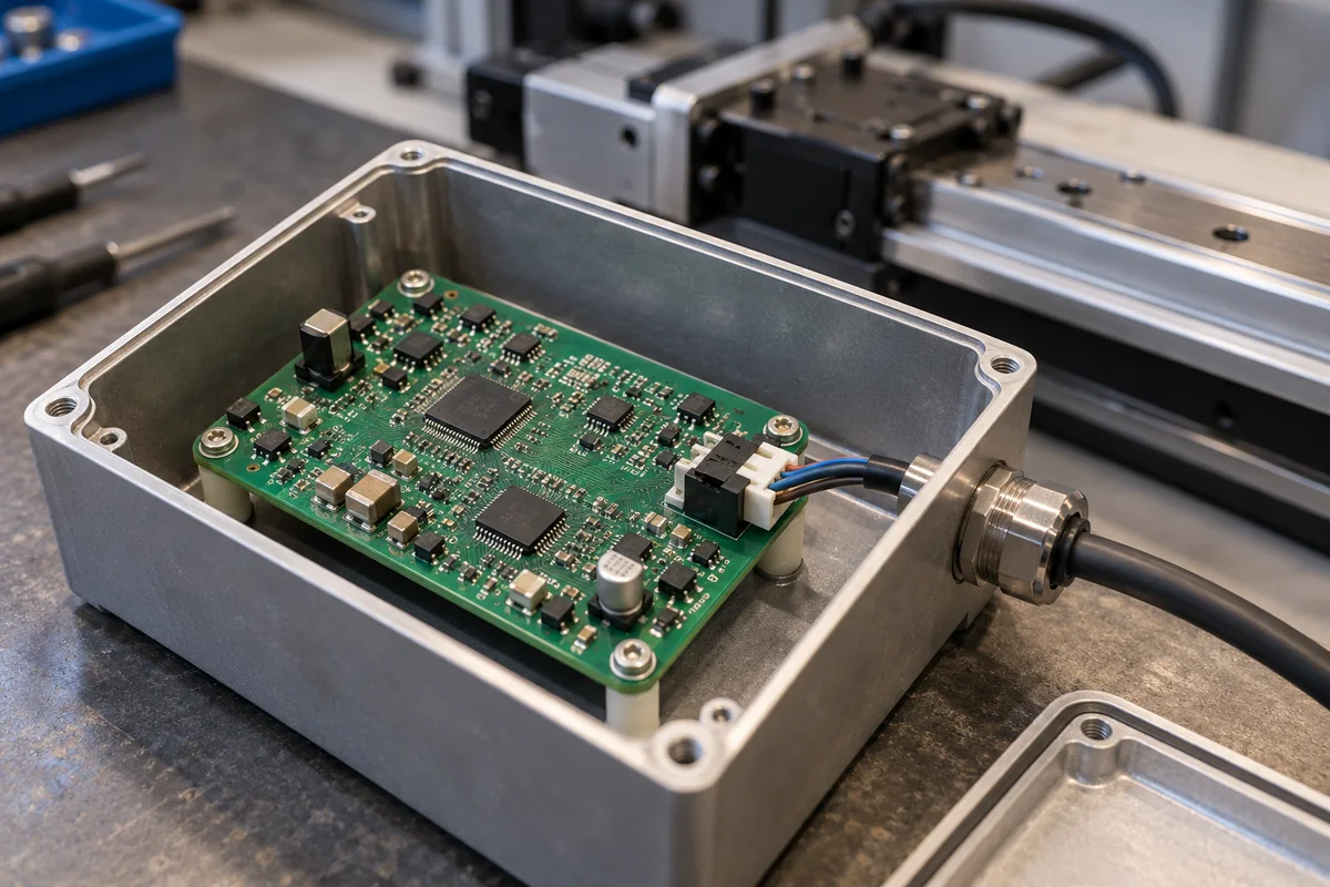
Signal-conditioning circuit board for LVDT position sensors: excitation, demodulation and output
Position sensor electronics · LVDT excitation, phase demodulation, output stage, and board-level versus DIN-rail builds
An LVDT position sensor is a transformer with a moving core, so it cannot report position on its own. A signal-conditioning board drives its primary coil with a stable AC voltage, reads the two secondaries, recovers core position and direction from their amplitude and phase, and delivers a DC voltage, a 4–20 mA loop or a digital value. The board's oscillator, demodulator and output stage set how much of the sensor's accuracy survives to the controller.
Signal-conditioning electronics for LVDT, RVDT and other AC inductive position sensors: circuit boards built into a sensor housing or a sealed enclosure, and DIN-rail conditioner modules, that excite the sensor, demodulate its secondaries and output a voltage, current-loop or digital position signal. Complete LVDT and magnetostrictive sensors are covered on the Position sensor (linear) page; contract board building is covered on the PCB assembly (PCBA) service page; MCU main control boards, communication interface boards and relay I/O boards are covered on their own pages; rotary encoders are covered on the High-resolution rotary encoder page; bridge amplifiers for strain-gauge load cells are covered on the Load-cell signal conditioner page; DIN-rail conditioners for thermocouple, RTD, current and voltage inputs are covered on the Industrial signal conditioner page; electronics heads of magnetostrictive sensors are covered on the Sensor head electronics module page.
CNFX editorial research · Sources checked October 12, 2026 · 3 sources
Primary excitation: oscillator frequency, drive current and amplitude feedback
Each channel of VPG's LVD 3 conditioner has an oscillator that drives the LVDT primary at 2.5–3.2 kHz with ±1% frequency stability, at most 4% distortion and up to 6 V AC at 150 mA, holding amplitude to ±0.1%. The secondary inputs present at least 150 kΩ so that they do not load the transducer, and accept up to 6.8 V. [1]
The LVD 3 can regulate its oscillator either from the primary voltage or from the mean of the two secondary voltages. VPG states that secondary feedback reduces the influence of temperature and cables on the measurement, but that transducers built with linearisation, whose mean secondary voltage changes with core position, must use primary feedback. [1]
Measurement Specialties' Schaevitz LDM-1000 offers jumper-selected oscillator frequencies of 2.5, 5.0 and 10.0 kHz at 1 or 3 V rms, a maximum LVDT drive of 25 mA rms, a minimum LVDT input impedance of 50 Ω at 1 V rms, phase correction for long cable runs, master/slave synchronisation of two or more LVDTs, and compatibility with four-, five- or six-wire sensors. [2]
Editorial calculation: at 3 V rms excitation the 25 mA rms drive limit implies a primary impedance of at least 3 / 0.025 = 120 Ω at the chosen frequency; a lower-impedance LVDT needs the 1 V rms setting. [2]
Send the LVDT's primary impedance and rated excitation frequency, its wiring (four, five or six wires), cable length, and whether two or more LVDTs sit close together and need synchronised oscillators.
02
Phase demodulation, filter bandwidth and the 4–20 mA or ±10 V output
In the LVD 3, the two secondary signals are phase-detected, combined into a bipolar signal and filtered to a DC voltage proportional to core position, with a −3 dB filter bandwidth of 125 Hz. Outputs are ±10 V or 0–10 V into more than 6 kΩ and 4–20 mA into less than 500 Ω, with ±0.05% linearity, offset drift of at most 2 mV and gain drift of at most 0.1%. [1]
The LDM-1000 lists ±5 V, 0–5 V and 0–10 V outputs and a 4–20 mA loop driven from its own internal loop supply, a frequency response of 250 or 1000 Hz at −3 dB, typical linearity of ±0.02% of full scale, and a temperature coefficient of less than ±0.04% per °C. It also offers 100% zero suppression so that a single-ended output covers the whole stroke. [2]
Editorial calculation: at the LDM-1000's temperature coefficient limit of 0.04% of full scale per °C, a 30 °C change in cabinet temperature could shift the output by up to 1.2% of full scale, far more than its 0.02% typical linearity. Ask for drift figures at your temperature range, not linearity alone. [2]
Editorial calculation: driving 20 mA through the LVD 3's maximum 500 Ω loop load needs 10 V of loop compliance, so long cable runs plus the PLC input resistance must stay under that load. [1]
Digital conditioning moves demodulation into converters: TI's PGA970 has a three-channel programmable-gain front end, three independent 24-bit delta-sigma ADCs (a dual ADC with amplitude and phase demodulators plus an auxiliary ADC), and a 14-bit output DAC, with SPI and one-wire interfaces for digital readout. [3]
03
A board inside the sensor enclosure or a DIN-rail module: supply range, temperature and size
A conditioner built as a board can sit in the sensor housing or a sealed box next to the axis, as long as it survives that environment. TI's PGA970 integrates the excitation waveform generator and amplifier, demodulation, an Arm Cortex-M0 for sensor compensation stored in 16 KB of FRAM, an on-chip temperature sensor and built-in diagnostics, runs from 3.5 V to 30 V with a gate controller for supplies above 30 V, and is rated for −40 °C to +125 °C ambient. [3]
Cabinet modules carry narrower ratings. The two-channel LVD 3 runs on 24 V DC ±20% at under 120 mA per channel, mounts on a 35 mm DIN rail with IP20 protection and is rated for 0–50 °C in operation. [1] The LDM-1000 runs from 10–30 V DC, is 22.5 mm wide on a DIN rail and is rated for −25 to +85 °C in operation. [2]
Editorial note: these ratings decide where the electronics can go. A 0–50 °C module stays in a controlled cabinet, so the LVDT's AC signals travel the whole cable length to it, which is why the modules offer cable-related features such as phase correction and secondary feedback; a board rated to +125 °C can sit beside the sensor and send a conditioned 4–20 mA or digital signal instead. [3][1][2]
State where the board will be mounted, the ambient temperature range, the supply available, enclosure protection and cable gland size, and whether calibration must be stored on the board.
04
Data for an LVDT conditioning board quotation
Paste it into your enquiry below or into an email to a maker, then replace every bracket.
Sensor: [LVDT or RVDT model; stroke; primary impedance; rated excitation; wires]
Excitation: [frequency; voltage; synchronisation between sensors]
Output: [±10 V, 0–10 V, 4–20 mA, SPI or other; load]
Dynamics: [bandwidth needed]
Accuracy: [linearity; drift over temperature]
Build: [board in enclosure or DIN-rail module; supply; temperature range; protection]
Explore company information and manufacturing capabilities, then discuss the scope of your project with a relevant supplier.
Share this page
Compiled and source-reviewed by the CNFX editorial team.
Each manufacturer above links to the page on that company's own website where the product is listed, with the date we checked it. How we source and review
· Page last updated 13 October 2026
Buyer questions
What excitation frequency does an LVDT conditioner use?
It depends on the conditioner and sensor: VPG's LVD 3 runs at 2.5–3.2 kHz; the Schaevitz LDM-1000 offers 2.5, 5.0 or 10.0 kHz. [1][2]
Why choose secondary feedback for the oscillator?
VPG says it reduces temperature and cable effects, but linearised transducers whose mean secondary voltage varies with position must use primary feedback. [1]
How fast can the output follow the core?
The LVD 3 filter is 125 Hz at −3 dB; the LDM-1000 offers 250 or 1000 Hz. [1][2]
Can the conditioning be done on a single chip?
Yes; TI's PGA970 combines excitation, 24-bit ADCs with demodulators, a Cortex-M0 and a 14-bit DAC, rated −40 to +125 °C from 3.5–30 V. [3]
Sources and what still needs a direct check
Sources checked 2026-10-12. Two sources are maker documents for specific DIN-rail conditioners (VPG Nobel LVD 3 and Measurement Specialties LDM-1000, both read from third-party hosted copies) and one is TI's datasheet for a conditioner chip; figures describe those products only.