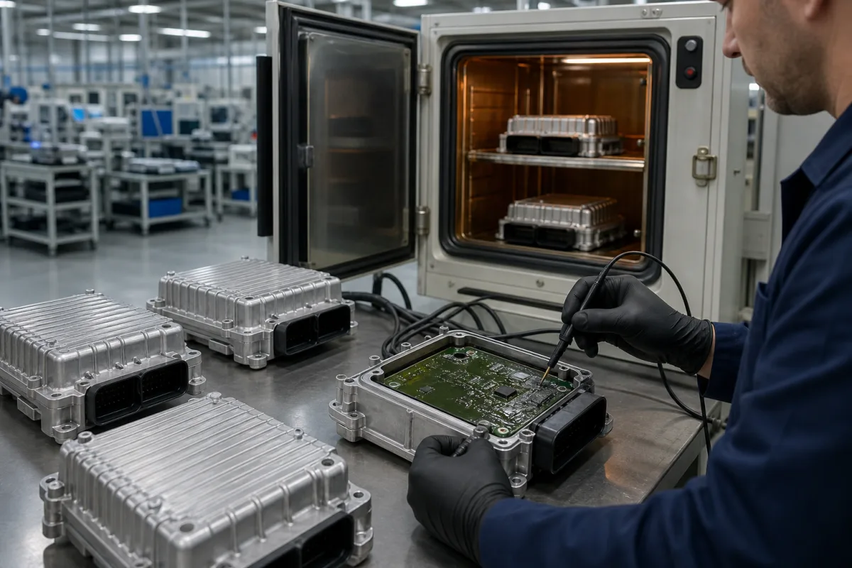
Sealed electronic control unit (ECU) for vehicles and mobile machines
Sealed ECUs for vehicles and mobile machines · 12/24 V supply, CAN and J1939, I/O count, IP6K9K, vibration, shock and functional safety
An electronic control unit (ECU) for a vehicle or mobile machine is a sealed controller, for example in a die-cast aluminium housing with automotive connectors, mounted on the chassis or body and powered from the 12 V or 24 V on-board supply. It reads sensors, drives valves, motors and lamps through its outputs and talks to other units over CAN. Ask three things first: how many inputs and outputs of each type and current the machine needs, which buses and protocols it must speak, and which environmental, electrical and functional-safety tests it has passed.
Sealed ECUs and mobile controllers for on-road vehicles, agricultural, construction and material-handling machines, with their I/O, communication, housing and test evidence. Cabinet-mounted PLC and motion control systems for factory machines are covered on the Industrial control systems page. Engine ECUs supplied only inside complete engines, dashboards and displays are outside this page.
CNFX editorial research · Sources checked October 12, 2026 · 3 sources
STW's ESX.4cl, a mobile-machine controller, lists up to 60 inputs and 53 outputs, six sensor supplies, six CAN interfaces (CAN 2.0B at 100 kbit/s to 1 Mbit/s), up to six Ethernet ports including 100BASE-T1 single-pair Ethernet, and an Infineon Aurix TC299 32-bit multicore processor at 300 MHz with 8 MB flash and 2 MB RAM. Its high-side outputs come in 4 A and 2 A types, each power supply pin is rated 12 A fully loaded, and its analog inputs read 0–12 V or 0–24 mA. [1]
A smaller unit shows the other end of the range: Epec's 3724 lists a 16/32-bit CPU, 1.6 MB flash, 52 I/O (24 inputs and 28 outputs), two CAN buses supporting CANopen, SAE J1939 and ISOBUS, 3 × AMP23 and 1 × AMP8 connectors, and CODESYS 2.3 programming. [2]
Editorial note: list each sensor and actuator with its signal type and current, then add spare channels; check that the outputs can switch your highest current coil or motor directly and that the buses match the engine, transmission and display already on the machine.
Give the supplier the machine, supply voltage (12 V, 24 V or both), each input and output with signal type and current, CAN buses and protocols, Ethernet needs, programming method, safety functions and required level, mounting position, connector preference, and the environmental tests you require.
02
Check sealing, vibration, shock and supply tests
STW lists the ESX.4cl's die-cast aluminium housing with a GORE-TEX breathing filter, IP6K6, IPX7 and IPX9K protection for the variant without M12 Ethernet connectors (IP6K5 and IPX7 with them), −40 to +85 °C housing temperature, −400 to 4,000 m altitude, 264 × 260 × 55 mm and about 1.7 kg. [1]
Its datasheet lists the tests behind those ratings: random vibration to IEC 60068-2-64 from 10 to 2,000 Hz for 32 hours per axis with temperature cycling, half-sine shock to IEC 60068-2-27 at 500 m/s² for 6 ms with 10 shocks per direction, a 1 m free-fall drop, salt spray to IEC 60068-2-52 severity 4, cyclic damp heat at +65 °C and 93% RH, ISO 16750-2 cranking and load-dump pulses for 24 V systems, and ISO 10605 ESD up to ±6 kV contact discharge. [1] Editorial calculation: 500 m/s² ÷ 9.81 m/s² ≈ 51 g.
On supply, STW gives an 8 to 32 V DC range, standby current below 1 mA with the ignition off, and about 500 mA at 12 V when active without external load for one variant. [1] Epec lists IP67 and −40 to +85 °C for the 3724. [2] Editorial note: ask for the test report of the exact connector and cable set you will use, since STW notes its ratings depend on connector variant.
03
Set the functional-safety level and software route
STW states the ESX.4cl is suitable for safety-related applications up to SIL 2 to IEC 61508:2010, PL d to EN ISO 13849-1:2015 and ASIL B to ISO 26262:2018 (the last a scheduled feature), and can be programmed in C, MATLAB Simulink or IEC 61131-3. [1]
For passenger-car body electronics, Huf states that its power sliding door control units meet ISO 26262 and AUTOSAR, connect over CAN or CAN FD, and include anti-pinch protection and protection against excessive current. [3] Editorial note: state the safety function, the required SIL, PL or ASIL, and whether the supplier or you will write and certify the application software.
04
I/O table, bus interfaces, environmental test reports and safety certificates to request
Ask each supplier for the I/O table, bus interfaces, test reports to the standards above, safety certification and software tools for the unit quoted.
05
Processor, inputs, high-side outputs, CAN and Ethernet, supply circuit, housing and software
Part
Role
Fix in the order
Processor and memory
Runs the application; e.g. 300 MHz, 8 MB flash. [1]
Supply range, ingress rating, vibration and shock profile and output current for a mobile-machine ECU
Ask for vibration and shock as test profiles with reports, not single figures: the ESX.4cl lists random 10–2,000 Hz for 32 h per axis and 500 m/s² for 6 ms. [1]
1 company lists this product among what they make. Company figures are quoted from each
company's own website; every card states where the relationship came from.
Huf Group
Manufacturing site to be confirmed for the order
Lists electronic control units for power sliding doors and Phone as a Key vehicle access, with CAN or CAN FD connection.
Explore company information and manufacturing capabilities, then discuss the scope of your project with a relevant supplier.
Share this page
Compiled and source-reviewed by the CNFX editorial team.
Each manufacturer above links to the page on that company's own website where the product is listed, with the date we checked it. How we source and review
· Page last updated 13 October 2026
Buyer questions
How is a mobile ECU different from an industrial PLC?
It is a sealed unit for a vehicle or machine: STW's ESX.4cl runs from 8–32 V DC, is rated IP6K6/IPX7/IPX9K and is tested to vibration, shock and ISO 16750-2 supply pulses. [1]
Which CAN protocols do mobile controllers support?
Epec lists CANopen, SAE J1939 and ISOBUS for its 3724 control unit. [2]
Can an ECU be used for safety functions?
STW states the ESX.4cl suits applications up to SIL 2, PL d and (scheduled) ASIL B; Huf states its sliding-door ECUs meet ISO 26262. [1][3]
Sources and what still needs a direct check
Sources checked 2026-10-12. STW's datasheet and Epec's product page are makers' published data for their mobile controllers; Huf describes its own vehicle ECUs. Figures are for the models named and must be confirmed for the unit you buy.