Editorial Technical Reference

Integrated Medical Imaging System Production Line

This page explains how Integrated Medical Imaging System Production Line is classified within Manufacture of Irradiation, Electromedical and Electrotherapeutic Equipment. Technical values and manufacturer relationships are research references; confirm the current specification and supplier evidence for each order.

Technical Definition & Core Assembly

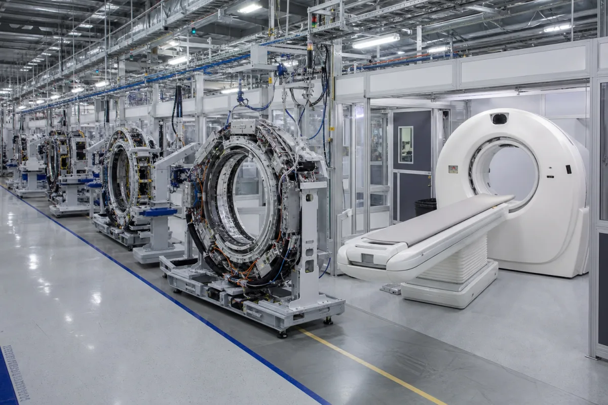
Automated production system for manufacturing medical imaging equipment components

Integrated Medical Imaging System Production Line in a manufacturing environment
Representative product image. Confirm appearance and specifications with the manufacturer.

Product Specifications

Technical details and manufacturing context for Integrated Medical Imaging System Production Line

Definition
The Integrated Medical Imaging System Production Line is an automated industrial system for manufacturing key components used in medical imaging equipment, such as X-ray generators, detectors, and imaging plates. It coordinates multiple specialized modules, including precision assembly stations, vacuum processing chambers, and quality verification systems, to produce electromedical components at high volume while maintaining strict medical device quality standards through automated process control and inline testing. The system operates through a coordinated sequence of automated stations where raw materials and subcomponents are processed, assembled, and tested under controlled environmental conditions. It is designed for manufacturers of irradiation, electromedical, and electrotherapeutic equipment. The production line integrates stations for precision assembly, vacuum processing, and quality verification, with automated process control and inline testing to ensure consistent output. It handles materials such as stainless steel 316L, medical-grade plastics, copper alloys, and ceramic insulators. Key parameters include a production cycle time of 120–180 seconds, a system footprint of 25–40 square meters, power consumption of 15–25 kW, vacuum levels of 0.1–1.0 mbar, temperature control range of 20–30 °C, operating pressure of 1.0–1.6 MPa, positioning accuracy of ±0.02 mm (per ISO 230-2), electrical supply of 380–480 V AC (per IEC 60038), operating humidity of 45–65% RH, ingress protection of IP54–IP65 (per IEC 60529), material grade 316L (per ASTM A240), and machine weight of 8000–12000 kg. These values are reference ranges and must be verified for the specific model and application. The system is intended for integration into existing manufacturing facilities, with interfaces for power, compressed air, and data communication. Verification questions should address actual performance under load, compliance with applicable standards, and validation of process parameters. Maintenance signals include deviations in cycle time, positioning accuracy, or vacuum integrity. Failure boundaries are defined by the system's operational limits, such as maximum power, pressure, and temperature ranges.
Working Principle
The system operates through a coordinated sequence of automated stations. Raw materials and subcomponents are fed into precision assembly stations where robotic arms align and join parts with high accuracy. Assembled units then pass through vacuum processing chambers where controlled pressure and temperature conditions are applied for processes like sealing or coating. Inline quality verification systems inspect each component using sensors and automated tests, ensuring they meet specifications. The entire sequence is managed by a central control system that monitors parameters and adjusts operations in real time to maintain consistency and quality.
Common Materials
Stainless Steel 316L, Medical-Grade Plastics, Copper Alloys, Ceramic Insulators
Technical Parameters
ParameterTypical rangeNotes & selection driver
Production Cycle TimeRequired120–180 secondsTime per complete production cycle
System FootprintRequired25–40 square metersTotal floor space required
Power ConsumptionRequired15–25 kWMaximum electrical power requirement
Vacuum LevelRequired0.1–1.0 mbarMinimum vacuum pressure in processing chambers
Temperature Control RangeRequired20–30 °COperating temperature range for thermal processes
Positioning Accuracy±0.02 mmFor robotic assembly and alignment.ISO 230-2
Electrical Supply380–480 V ACThree-phase, 50/60 Hz; 10% tolerance.IEC 60038
Operating Humidity45–65 % RHNon-condensing; above 65% risk of corrosion.
Ingress ProtectionIP54–IP65For control cabinets and motors.IEC 60529
Material Grade316LFor all wetted parts; corrosion-resistant.ASTM A240
Machine Weight8000–12000 kgIncluding base frame and shielding.

Ranges are indicative industry figures for RFQ preparation, not a supplier commitment. Confirm every value and standard with the legal manufacturer before ordering.

Components / BOM

Industry Taxonomies & Aliases

Commonly used trade names and technical identifiers for Integrated Medical Imaging System Production Line.

Industrial Ecosystem & Supply Chain Structure

Complementary Systems
Downstream Applications
Specialized Tooling

Application Fit & Sizing Matrix

Operational Limits
pressure: Atmospheric to 2 bar (clean dry air systems)
flow rate: 0.5-5.0 m³/min (pneumatic conveyance)
temperature: 15-30°C (controlled environment)
particulate level: ISO Class 7 cleanroom or better
vibration tolerance: <0.5 mm/s RMS (precision alignment sensitive)
slurry concentration: Not applicable (clean assembly environment)
Media Compatibility
✓ Medical-grade plastics (PEEK, Ultem) ✓ Stainless steel 316L components ✓ Ceramic imaging detector materials
Unsuitable: Corrosive chemical processing environments
Sizing Data Required
  • Annual production volume (units/year)
  • Component size/dimensions range (mm)
  • Required imaging modality mix (CT/MRI/X-ray ratio)

Reliability & Engineering Risk Analysis

Failure Mode & Root Cause
Optical Component Degradation
Cause: Accumulation of dust, moisture ingress, or misalignment from vibration during production line movement, leading to reduced image clarity and calibration drift.
Mechanical Actuator Wear
Cause: Repeated high-precision positioning cycles under load, causing fatigue in bearings, leadscrews, or belts, resulting in positional inaccuracies and increased backlash.
Maintenance Indicators
  • Audible grinding, clicking, or irregular motor noises from positioning mechanisms during operation.
  • Visual artifacts, blurring, or inconsistent image quality in system calibration checks or test outputs.
Engineering Tips
  • Implement a predictive maintenance program using vibration analysis and thermal imaging to monitor actuator health and detect early wear before failure.
  • Establish strict environmental controls (cleanroom standards, humidity regulation) and regular optical alignment protocols to prevent contamination and misalignment.

Indicative industry ranges for design and RFQ preparation. Confirm the exact figures and applicable standard with the manufacturer before specifying.

Compliance & Manufacturing Standards

Applicable Standards
IEC 60601-1:2005 - Medical electrical equipment - Part 1: General requirements for basic safety and essential performance FDA 21 CFR Part 820 - Quality System Regulation

Quoted from the published standard.

Manufacturing Precision
  • Optical alignment: +/- 0.005 degrees angular deviation
  • Mechanical positioning repeatability: +/- 0.1mm linear displacement
Quality Inspection
  • Electromagnetic Compatibility (EMC) testing per IEC 60601-1-2
  • Image quality verification using standardized phantoms per IEC 61223-3-5

Manufacturers of Integrated Medical Imaging System Production Line

Manufacturer profiles associated with Integrated Medical Imaging System Production Line.

Sourcing Integrated Medical Imaging System Production Line from China?
Tell us your specification and target quantity — we will match it against manufacturer records and come back with the factories that fit.
Request manufacturers We manufacture this

Manufacturer listings support early research and capability understanding. They are not certification, ranking, or transaction guarantees.

Share this page
Technical documentation
Request current drawings, revision history, and a signed specification sheet.
Manufacturing capability
Verify equipment lists, process limits, capacity, and representative production evidence.
Inspection readiness
Confirm test methods, calibrated equipment, sampling plans, and traceable reports.
Supplier transparency
Check the legal entity, factory address, ownership, certifications, and direct contacts.

CNFX does not score or rank suppliers. Buyers must verify all claims and documents with the legal manufacturer before ordering.

Frequently Asked Questions

What types of components can this production line manufacture?

The production line is designed for key components used in medical imaging systems, such as X-ray generators, detectors, and imaging plates. The specific component types depend on the configured modules and tooling.

What are the main modules included in the system?

The system includes precision assembly stations, vacuum processing chambers, and quality verification systems. These modules work together to automate the manufacturing process.

What are the utility requirements for installation?

The system requires an electrical supply of 380–480 V AC (three-phase, 50/60 Hz, 10% tolerance) and a maximum power consumption of 15–25 kW. It also needs a floor space of 25–40 square meters and operates within a temperature range of 20–30 °C and humidity of 45–65% RH.

How is quality control ensured during production?

Quality control is achieved through automated process control and inline testing protocols. The system continuously monitors parameters such as positioning accuracy, vacuum level, and temperature, and performs inspections at various stages to ensure components meet specifications.

Data Basis

Editorial classification, named public sources where available, and source-reviewed manufacturer records.

Preliminary Technical Classification
This page supports structured research, RFQ preparation, and supplier evaluation. It does not replace buyer-led supplier qualification, standards review, or technical approval.
Buyer enquiry

Request manufacturing insight for Integrated Medical Imaging System Production Line

Ask for use case, specification boundaries, supplier type, and RFQ preparation information for this product.

Where it goes
Straight to the CNFX editorial desk, and to the manufacturer if this product is linked to a claimed profile. Nothing is broadcast to a supplier list.
Your details stay here
We do not sell or rent enquiry data, and we do not add you to a mailing list. Used only to answer this request.
No commission, no middleman
CNFX is a directory. We take no cut of any order and never negotiate on a supplier's behalf.
What we don't claim
A listing is not an endorsement. Qualify every supplier and verify every figure yourself before ordering.

Your business information is used only to process this request.

Thank you! Your message has been sent. We'll respond within 1–3 business days.
Sorry, we couldn't send your message. Please try again, or email us at [email protected].

Need to Manufacture Integrated Medical Imaging System Production Line?

Compare manufacturer profiles with relevant product and process capability.

First Product
Next Product
Integrated Radiotherapy Linear Accelerator Assembly System
Get QuotesChat