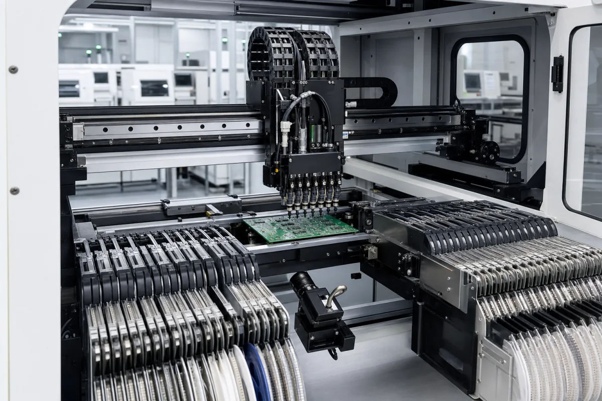
Pick-and-place robot component vision: laser, upward-camera and line-scan centering that measures every part between pick and place
How a pick-and-place robot sees each part between the feeder and the board · laser sensors on the head, upward-looking area cameras and line-scan cameras, and the pitch, size and height limits each one sets
A part never sits exactly centered on the nozzle that lifts it from the tape. Between pick and place the robot measures where the part really is, how far it is rotated, and on better systems whether its leads or balls are all present and level; the head then corrects X, Y and angle before setting it down. Two parts of the same size can need different sensors: a small chip can be centered on the fly by a laser on the head, while a fine-pitch QFP or BGA needs a camera that can resolve each lead or ball.
The component recognition system of SMT pick-and-place robots: head-mounted laser centering sensors, upward-looking area cameras with fixed fields of view, line-scan cameras, coplanarity and thickness sensing, and the component size, pitch and height limits they set. The complete placement machine and its rate and accuracy are covered on the SMT pick-and-place machine page; head types and nozzle counts on the Automated high-speed SMT chip mounter and SMT placement head pages; the gantry axes on the XY motion system of an SMT placement machine and XY gantry system pages; tape feeders on the Component feeder page; board inspection after placement on the AOI and post-placement inspection pages; and camera and laser height sensing for optical lens loaders on the Vision/sensor system for lens loading page.
CNFX editorial research · Sources checked October 13, 2026 · 3 sources
Laser on the head or camera under the head: JUKI centers 03015 to 50 mm parts by laser and switches to 10, 27 or 54 mm camera fields for the rest
JUKI's RS-1R carries both kinds of sensor, which makes it a useful reference for what each one covers:
Editorial calculation: a 25% cut in centering time means a sequence that took 0.4 s on the 54 mm camera would take about 0.3 s when four parts share one image; the 0.4 s here is an example value, not a JUKI figure. [1]
JUKI also feeds the centering result back into the pick: its pick-position auto-correction adjusts the feeder pick position from the centering results, which JUKI says improves simultaneous picking and throughput. [1] For LED diffusion lenses, the RS-1R can use either laser or vision centering depending on the part. [1]
Item
Laser centering (on the head)
Vision centering (VCS camera)
Component range
03015 metric to 50 mm square SOP, PLCC and QFP [1]
Down to 0201 metric with the 10 mm field-of-view camera; machine range up to 74 mm square or 50 × 150 mm [1]
How it measures
Measures centre, angle, width, depth and height of each part; JUKI says it is not affected by variations in component colour or shape [1]
Captures shape, lead and ball details; detects missing balls and bent leads; three-colour lighting; front/back detection [1]
When it measures
On the fly: 8 nozzles centered at once while the head moves from pick to place [1]
54, 27 or 10 mm fields of view; the 54 mm camera can center up to 4 parts in one image, which JUKI says cuts centering time by 25%; strobing with the 10 and 27 mm cameras [1]
Height handling
Laser height moves to one of 6 positions (1, 3, 6, 12, 20, 25 mm) to suit the part height [1]
Dirty laser is flagged before production starts [1]
Upward-looking camera condition is checked before production starts [1]
List the smallest and largest parts, the finest lead or ball pitch, the tallest part, and whether lead or ball presence must be checked before placement; ask which sensor centers each part class and at what field of view.
02
What the camera resolves: 4K line-scan to 0.10 mm pitch against 0.20 mm for 2K, and Panasonic's 2D, thickness and 3D coplanarity in one camera
The pitch a camera can resolve and the size it can see in one pass decide which packages a machine can place without help from a second sensor.
Editorial calculation: moving from 2K to 4K line-scan on the MY300EX halves the minimum leaded pitch (0.20 mm to 0.10 mm) and raises the largest component width from 56 mm to 73 mm, about 30% more (73 ÷ 56). [3]
Recognition is one link in the placement accuracy a maker states, and the makers state it on different bases. Panasonic gives ±40 μm per chip in high-production mode and ±30 μm (±25 μm as an option) in high-accuracy mode at Cpk ≥ 1 for the 16-nozzle head [2]; JUKI gives ±35 μm at Cpk ≥ 1 for the RS-1R [1]; Mycronic gives 50 µm and 2.6° chip accuracy at Cpk = 1.33, which it defines as 4σ plus offset. [3] A figure at Cpk 1.33 is a stricter statement than the same number at Cpk 1, so compare the basis before the number.
Machine and sensor
Stated limit
Mycronic MY300EX, line-scan vision 4K
Leaded parts: 0.10 mm minimum pitch, 0.05 mm minimum lead width; bumped parts: 0.15 mm pitch, 0.08 mm lead width [3]
Mycronic MY300EX, line-scan vision 2K
Leaded parts: 0.20 mm pitch, 0.10 mm lead width; bumped parts: 0.25 mm pitch, 0.13 mm lead width [3]
Mycronic MY300EX, largest component
140 × 73 × 35 mm with 4K vision; 140 × 56 × 35 mm with 2K vision [3]
Panasonic NPM-W2, multi-recognition camera
Three recognition functions in one camera; recognition scan includes component height detection; upgradable from 2D to 3D [2]
Coplanarity sensor; Component Verification System [1]
Send the package list with pitch, lead width and ball size for the finest parts, and ask for the recognition method, field of view or line-scan resolution, and coplanarity option that the quoted machine uses for each.
03
Recognition details to include
Paste it into your enquiry below or into an email to a maker, then replace every bracket.
Smallest part: [metric size]
Largest part: [L × W × H]
Finest pitch: [leaded; bumped; lead width]
Checks before placement: [coplanarity; missing balls; bent leads; polarity; face up/down]
Odd-form parts: [connectors; LED lenses; shields]
Accuracy needed: [μm at which Cpk]
Explore company information and manufacturing capabilities, then discuss the scope of your project with a relevant supplier.
Share this page
Compiled and source-reviewed by the CNFX editorial team.
Each manufacturer above links to the page on that company's own website where the product is listed, with the date we checked it. How we source and review
· Page last updated 13 October 2026
Buyer questions
What is laser centering on a pick-and-place machine?
A laser sensor on the head measures each picked part's centre, angle and size while the head travels; JUKI's RS-1R does this for parts from 03015 metric to 50 mm square, eight nozzles at a time. [1]
What lead pitch can a pick-and-place camera resolve?
Mycronic gives 0.10 mm minimum pitch for leaded parts with its 4K line-scan vision and 0.20 mm with 2K vision on the MY300EX. [3]
Can a pick-and-place machine check coplanarity?
Yes, as an option on some machines: JUKI lists a coplanarity sensor for the RS-1R, and Panasonic's NPM-W2 camera can be upgraded from 2D to 3D with a 3D sensor option. [1][2]
Sources and what still needs a direct check
Sources checked 2026-10-13. Three maker specification documents: JUKI's RS-1R specification and feature sheet, Panasonic's NPM-W2 brochure and Mycronic's MY300EX specification.