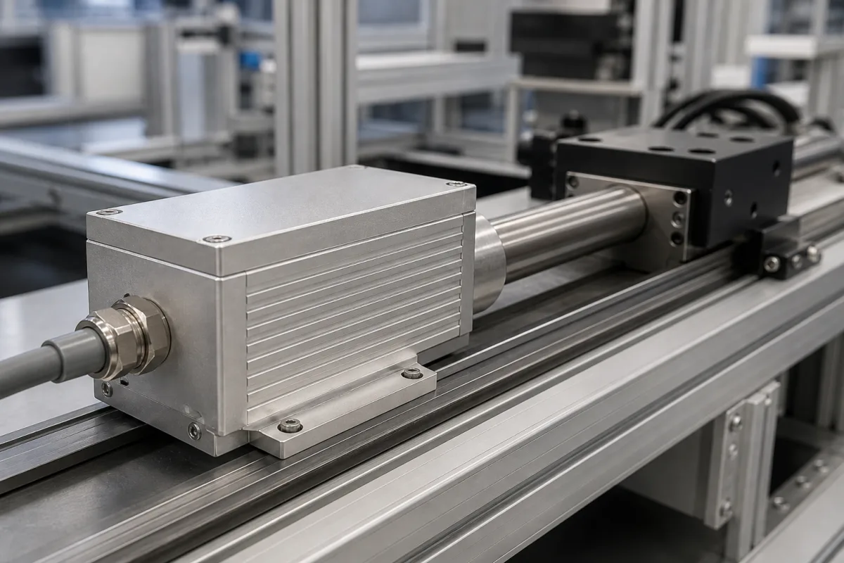
Sensor head electronics module for magnetostrictive position sensors: detector unit, output interface and in-place replacement
The electronics head as a module of a magnetostrictive position sensor · detector coil and evaluation circuit, output interfaces from start/stop to SSI and EtherCAT, diagnostics, and electronics replaced without opening the cylinder
In a magnetostrictive linear position sensor the moving part is only a permanent magnet; everything that measures sits in the sensor head at one end of the rod or profile. The head electronics launch a current pulse along a ferromagnetic waveguide, pick up the torsional strain pulse that the magnet's field releases, time the interval and either output that interval as pulses or convert it into an analogue value or a digital position word. What a buyer has to settle about the head is the output interface and resolution, the linearity and temperature behaviour, the dead zone next to the head, and whether the electronics can be exchanged without dismantling the machine or cylinder.
The electronics head of magnetostrictive linear position sensors treated as a module: detector unit and evaluation circuit, output interface and resolution, diagnostics, housing, and replacement or detached mounting of the electronics. Complete magnetostrictive sensors — sizing the rod from stroke, null and dead zone, housing types and the waveguide timing principle — are covered on the Position sensors page. DIN-rail analogue signal conditioners and isolators are covered on the Industrial signal conditioner page; strain-gauge bridge amplifiers are covered on the Load-cell signal conditioner page; pyrometer signal processors and pulse-to-analogue converters for flowmeters are separate pages.
CNFX editorial research · Sources checked October 12, 2026 · 3 sources
Detector coil and evaluation circuit: what sits inside the head module
ASM's patent addresses the detector unit in the head. It notes that conventional detector coils, for which the number of turns matters, are relatively large, and instead forms the detector coil as a flat coil in a semiconductor chip together with signal conditioning, filtering, regulation and noise suppression. It names at least 50 turns, a coil diameter of at most 2 mm, a chip no larger than 2.5 mm in plan view and a coil-to-waveguide distance of at most 0.20 mm, and argues that the short on-chip connections make the detector unit more EMC-resistant than a PCB solution. [3]
The same patent describes the element the coil reads: a waveguide or Villari tape of nickel alloy or constant-modulus alloy strip about 0.05–0.2 mm thick and 0.5–1.5 mm wide, in which the torsional pulse travels at about 2,500 to 6,000 m/s depending on the material's elastic or shear modulus. [3] Editorial calculation: a 1 µm position step then corresponds to 1 µm ÷ (2,500 to 6,000 m/s), about 0.17 to 0.4 ns, the time scale the evaluation circuit works on; this is not a statement of how any maker resolves it.
Temposonics lists the supporting electronics as one of four parts of each sensor, with the waveguide, the position magnet and the strain pulse converter, and describes double-shielded construction for EMI immunity in its R-Series. [1]
Ask the supplier where the detection and timing take place (in the head, or in the controller for start/stop outputs), the update rate for your stroke length, and the null zone and damping zone at each end of the stroke.
02
Output interface, accuracy and replaceable electronics in the head
The interface chosen for the head decides who does the timing. Balluff's BTL6-P111 profile transducer outputs start/stop pulses through a +5 V RS-485/422 driver and lists resolution and repeat accuracy of ≤ 10 µm, non-linearity of ±200 µm, a typical temperature coefficient of ≤ 35 ppm/K, current consumption of ≤ 90 mA at 24 V DC, 0 to 70 °C ambient and a 73 mm null point, in an anodised aluminium housing rated IP67 with connector. [2] Editorial note: with a start/stop output the interval between the two pulses is measured by the receiving controller or interface card, so the resolution achieved also depends on that counter; ask whether your controller has a matching input.
Temposonics states that the modular design of its R-Series V, R-, G- and GB-Series allows the sensing element and electronics to be replaced without breaking the cylinder's high-pressure seal, and that on the GB-Series with threaded flange the electronics housing can be rotated through 360° and the sensor element and electronics replaced while the flange stays in the cylinder. It also lists an RD4 version with detached sensor electronics. [1]
For R-Series V, Temposonics adds that status and statistical data, including internal sensor temperature, operating hours and the distance travelled by the position magnets, can be read through its TempoLink assistant over the power supply connection while the sensor operates. [1] Editorial calculation: Temposonics' < 0.01 % F.S. linearity on a 5,000 mm stroke is 0.5 mm, while on a 500 mm stroke 0.01 % is 50 µm, so below about 500 mm the ±50 µm floor governs.
Specify stroke length, interface and resolution, linearity in µm at your stroke, supply voltage, ambient temperature at the head, IP rating, connector or cable exit, and whether the electronics must be exchangeable without opening the cylinder.
03
Describe the stroke, the interface and how the head will be serviced
Paste it into your enquiry below or into an email to a maker, then replace every bracket.
Sensor style: [rod in hydraulic cylinder; profile on machine]
Stroke: [mm; null zone and damping zone available]
Output: [analogue; SSI; start/stop; fieldbus]
Resolution and linearity: [µm; % F.S.]
Environment at the head: [temperature; pressure; IP rating; shock and vibration]
Service: [electronics replaceable in place; detached electronics]
Supply: [V DC; current]
Explore company information and manufacturing capabilities, then discuss the scope of your project with a relevant supplier.
Share this page
Compiled and source-reviewed by the CNFX editorial team.
Each manufacturer above links to the page on that company's own website where the product is listed, with the date we checked it. How we source and review
· Page last updated 13 October 2026
Buyer questions
What is inside the electronics head of a magnetostrictive sensor?
The detector unit that picks up the strain pulse and the evaluation circuit; ASM's patent puts a flat detector coil of at least 50 turns and the signal conditioning on one chip of at most 2.5 mm. [3]
How fast does the strain pulse travel?
About 2,500 to 6,000 m/s depending on the waveguide material's modulus, according to ASM's patent. [3]
Can the electronics be replaced without opening a hydraulic cylinder?
Temposonics states that its R-Series V, R-, G- and GB-Series allow the sensing element and electronics to be replaced without breaking the cylinder's high-pressure seal. [1]
What is a start/stop output?
An output of start and stop pulses whose interval represents position; Balluff's BTL6-P111 sends them through a +5 V RS-485/422 driver, with up to 2 magnets. [2]
Sources and what still needs a direct check
Sources checked 2026-10-12. The Temposonics selector guide (MTS Sensors) and Balluff's BTL6-P111 data sheet give published data for specific sensor heads; ASM's US patent 11,867,536 describes waveguide materials, strain-pulse speed and detector-coil design. Other sensors differ; ask for the data sheet of the model offered.