Vision camera system for coordinate measuring machines: the imaging probe and how ISO 10360-7 tests it
Imaging probes on vision and multi-sensor CMMs · ISO 10360-7 length, squareness and PF2D probing tests, field of view against stand-off and depth of field, vision and touch data on one datum
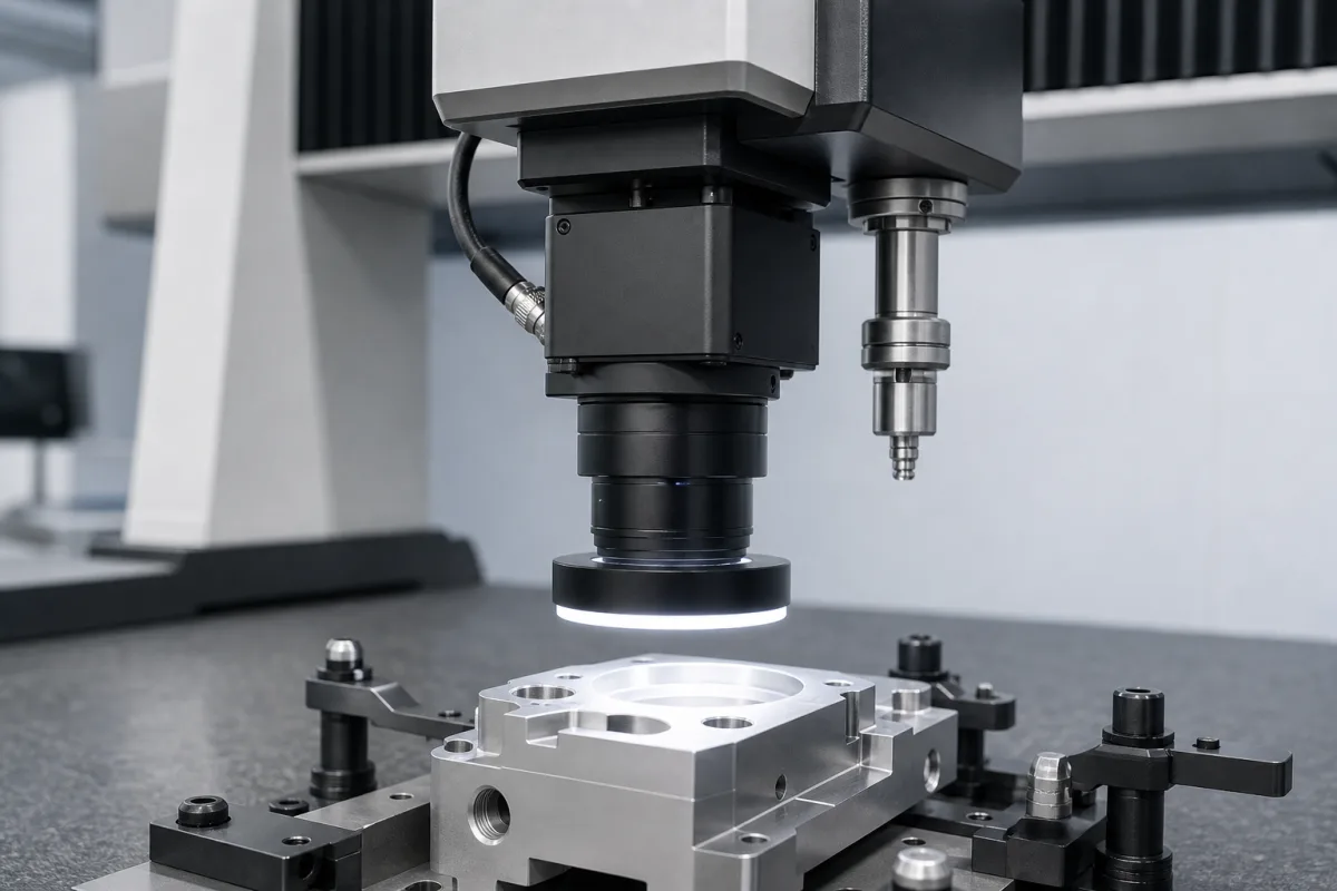
On a vision measuring machine or a multi-sensor coordinate measuring machine (CMM), the vision camera system is the imaging probe: an image sensor, a lens or optical module and its lighting, carried on the machine's Z axis, with software that finds edges in the image and turns them into measured points. What a buyer needs from it is different from what a factory-line camera is judged on: which ISO 10360-7 maximum permissible errors the machine is stated to with this probe, what field of view, stand-off and depth of field each optical module gives for the feature sizes on the part, and how its points are tied to the touch probe's on the same machine.
Imaging probing systems for vision measuring machines and multi-sensor CMMs: the camera, optical modules or zoom lens, integral and back lighting, and their acceptance testing under ISO 10360-7. Area-scan and line-scan machine-vision cameras with GigE Vision, USB3 Vision or CoaXPress interfaces are covered on the Industrial camera for machine vision page, and self-contained inspection cameras with on-board programs and I/O on the Industrial smart camera module page. Camera-based material recognition on cutting and marking machines, optical distance and laser line sensors (ISO 10360-8) and touch probes are outside this page. Bridge and gantry measuring machines as whole machines, specified by their ISO 10360-2 length error and room conditions, are on the Coordinate measuring machines (CMM) page.
CNFX editorial research · Sources checked October 12, 2026 · 4 sources
ISO 10360-7: the length, Z-squareness and PF2D numbers a vision CMM is stated to
Mitutoyo's James Salsbury, who led the task force that wrote ISO 10360-7:2011, describes it as the first international standard for testing CMMs fitted with any type of imaging probing system, such as video or vision measuring instruments. It applies only to Cartesian CMMs using imaging probes in discrete-point mode, and it gives the maker a choice of two length-test approaches. [1]
The U and B in each symbol say whether the artifact was measured unidirectionally (for example linescale pitch or centre-to-centre distance of circles) or bidirectionally (widths, opposing edges, circle size). The standard does not recommend one over the other. [2] Salsbury also notes that MPE values from the composite and component approaches cannot necessarily be compared directly. [1]
The Mitutoyo presentation gives an example of how a maker states these limits: EUXY,MPE = 0.5 + 2L/1000 and ESQ,MPE = 2.5. The micro sign is lost in the published text; the values read as micrometres with L in millimetres. Editorial calculation on that example: over a 100 mm length the EUXY limit is 0.5 + 2 × 100 ÷ 1000 = 0.7 µm. [2]
Specification
What is measured
Artifact and sampling
EUXY,MPE or EBXY,MPE (component)
Lengths in the XY plane along four lines: parallel to X, parallel to Y and the two planar diagonals. [2]
Linescale; 5 lengths × 3 repeats on each line, 60 values. [2]
Ask the supplier which approach and which U or B specifications the machine is stated to, the PF2D value, the optical module or zoom setting the values apply to, and the temperature range of the statement.
02
Why a "2D" vision measurement still depends on the Z axis
Salsbury points out that measuring the distance between two bores at different heights means projecting features into one plane while the Z axis moves up or down, so the Z axis's error motion relative to the XY plane, dominated by its squareness, enters what looks like a two-dimensional result. ISO 10360-7 therefore includes the ESQ squareness test. [1]
Mitutoyo's presentation calls this a 2½-D measurement and states that if 3D volumetric length tests are not being done, the squareness test is critical. It also notes that the composite EU or EB test requires measuring an inclined linescale with the vision probe. [2]
For the PF2D probing test, the same presentation lists what it checks: optics, camera alignment and edge-detection software, with machine motion. It adds that a sufficiently round 2D circle artifact is hard to obtain and calibrate, and that Mitutoyo developed a special glass chart for the test. [2] Editorial note: ask which artifact and calibration were used for the PF2D figure quoted.
03
Field of view, stand-off and depth of field against the smallest feature
Renishaw's RVP vision probe for its REVO-2 five-axis head shows how one camera body is matched to feature size by interchangeable optical modules, each with its own LED ring. The camera is a 1/1.8" CMOS sensor in a 551 g probe body. [3]
Renishaw's feature-size error, measured on a calibrated glass artifact (uncertainty ±0.5 µm) with backlighting, is 3 µm on a 25 mm circle and 2 µm on 10 mm and 2 mm circles with VM10, and 1 µm on 10 mm and 2 mm circles with VM11-2; the VM12 value is listed as TBC. [3]
Editorial calculation: the VM12 field of view (3.1 × 2.5 = 7.75 mm²) is about 1/258 of the VM10's (50 × 40 = 2,000 mm²), and its depth of field is 0.2 mm against 5 mm, so the small-feature module needs the part height known to within a fraction of a millimetre or a focus search at each feature. [3]
All RVP modules carry integral LEDs for contrast between holes and part material, and backlighting with part fixturing is offered for silhouettes. [3] Editorial note: on any vision probe, ask whether the stated errors were measured in transmitted (back) light, as Renishaw's were, or in reflected light on a machined surface like the part you will measure.
Vision and touch probes on one machine: separate MPEs, one datum
On a multi-sensor CMM the vision probe's specifications sit beside the touch probe's. Salsbury's comparison table assigns E0,MPE (ISO 10360-2) and PFTU,MPE (ISO 10360-5) to the touch probe and PF2D,MPE (ISO 10360-7) to the vision probe. [1]
Renishaw's RVP tests were run on a machine stated to MPE(E150) 3 µm + L/333 mm and MPE(PFTU) 1.6 µm, and the RVP is automatically interchangeable with REVO-2's other probes, with data from all sensors referenced to one shared datum. [3]
Bores and side features need the camera's view turned: Renishaw's ACM accessory is a first-surface mirror that rotates the VM11-2 field of view through 90°, keeping the 12.5 × 10 mm field, 5 mm depth of field and 20 µm resolution, with 34 mm stand-off from the mirror centre. It mounts magnetically on a kinematic ring and weighs 33 g. [4]
State the smallest and largest feature, the material and finish, whether the feature can be backlit, the heights the camera must focus across, and which features must be related to touch-probed datums.
05
Send the features, the specification approach and the probe mix
Paste it into your enquiry below or into an email to a maker, then replace every bracket.
Features: [smallest and largest diameter or width; edge type; material and finish]
Lighting: [backlight possible; reflected only]
Heights: [range of Z the camera must focus on]
Accuracy: [ISO 10360-7 approach; EUXY or EU; ESQ; PF2D values needed]
Modules or zoom: [fields of view; stand-off; depth of field]
Other probes: [touch probe; ISO 10360-2/-5 values; shared datum]
Access: [bores or side walls needing a mirror or tilting head]
Explore company information and manufacturing capabilities, then discuss the scope of your project with a relevant supplier.
Share this page
Compiled and source-reviewed by the CNFX editorial team.
Each manufacturer above links to the page on that company's own website where the product is listed, with the date we checked it. How we source and review
· Page last updated 13 October 2026
Buyer questions
Which standard tests a vision CMM?
ISO 10360-7:2011 covers Cartesian CMMs with imaging probing systems in discrete-point mode, with component (EUXY, EUZ, ESQ) or composite (EU or EB) length tests and the PF2D probing test. [1]
What is the PF2D test?
A circle calibrated for roundness is measured with 25 points spread across the field of view while the machine moves between points; the form of the fitted circle is the PF2D value. [1]
How small a feature can a vision probe measure?
Renishaw lists 1 mm for its RVP VM10 module with a 50 × 40 mm field of view, 0.4 mm for VM11-2 and 0.05 mm for VM12 with a 3.1 × 2.5 mm field and 0.2 mm depth of field. [3]
Can a vision probe look into a bore?
Renishaw's ACM mirror turns the VM11-2 field of view through 90° for bore surfaces, with 34 mm stand-off from the mirror centre. [4]
Sources and what still needs a direct check
Sources checked 2026-10-12. Two Mitutoyo education documents by the leader of the ISO 10360-7 task force explain the tests, explicitly not as an official interpretation; Renishaw's data sheets give one vision probe family's optics and errors. Other machines differ, so ask for the same values for the probe and machine quoted.