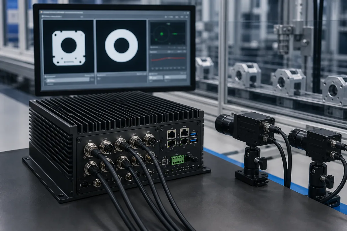
Image processing unit with built-in LED strobe control: a fanless vision box that triggers the cameras and drives the inspection lights itself
Fanless vision box with built-in LED strobe outputs · 24 V at 1 A per channel in strobe mode, trigger I/O under 1 µs, PoE camera ports sharing a 30 W budget
This kind of image processing unit puts LED driver outputs, trigger inputs and outputs and encoder inputs in the same fanless box that runs the inspection software, so one unit decides when a part is in place, fires the camera, pulses the light for the exposure and reads the result. Before choosing one, check three things: how much current each light output can deliver and in which mode, how fast the trigger chain is from sensor to flash, and whether the power input and PoE budget can carry the cameras and the light pulses together.
Industrial image processing units (vision boxes and vision computers) with integrated LED lighting control outputs and real-time trigger, strobe and encoder I/O, and the timing and power questions that integration raises. Vision controllers chosen mainly by camera port count, bandwidth and line protocols are covered on the Vision processing unit page; GPU module vision controllers for deep-learning inspection on the AI vision controller page; complete inspection systems with cameras, lenses and lighting on the Machine vision system for inspection page; stand-alone LED lights and strobe controllers on the LED lighting system for machine vision page; synchronised multi-camera arrays on the Vision camera array page; smart cameras on the Industrial smart camera module page; frame grabbers and PoE interface boards on their own pages.
CNFX editorial research · Sources checked October 12, 2026 · 4 sources
Strobe mode at 1 A, trigger mode at 0.5 A: what four built-in 24 V LED channels can and cannot drive
Axiomtek's MVS900-511-FL shows the arrangement in one datasheet: a fanless box for 6th and 7th generation Intel Core processors with four PoE GbE camera ports and four LED lighting control channels, each rated 24 V and 1 A per channel in strobe mode or 24 V and 0.5 A per channel in trigger mode. [1]
Editorial calculation: 24 V × 1 A = 24 W per channel while a strobe pulse is on, and 24 V × 0.5 A = 12 W per channel in trigger mode, or 96 W and 48 W if all four channels fire at once (datasheet ratings; the actual draw depends on the light connected). [1]
The datasheet does not say how the output current is regulated, so ask whether each channel sets a constant current or switches the 24 V supply on and off, and whether the current is adjustable. [1] Texas Instruments' reference design for machine vision LED control shows what a regulated channel offers: a dedicated buck LED driver delivering a programmable constant current of 200 mA to 2.4 A in 50 mA steps into an LED string of up to 24 V, which it describes as a direct measure of light brightness and as the way to overdrive LEDs safely during short pulses. [2]
Lights that need more current than the box can supply are driven through an external stage. Basler's Driver Board 2x2 use case, for example, connects a 24 V flash light without internal controller drawing up to 4 A to the board's LightB driver outputs and switches it from the camera's Line 3, a load four times the 1 A strobe rating of a single Axiomtek channel. [4][1]
For each light, write down its voltage, its current in continuous and pulsed operation, whether it has its own internal controller, and the pulse width you expect to use; then match it to a channel's strobe or trigger rating.
02
From part sensor to flash: trigger inputs under 1 µs, a 10 µs driver delay and the camera's flash window
The MVS900-511-FL lists four trigger inputs and four trigger outputs with a response time under 1 µs, sink type and 0 to 30 V range (outputs open collector, 100 mA maximum per channel), two quadrature encoder inputs with A, B and Z signals, 8 isolated digital inputs and 8 isolated outputs, and programmable interrupt functions. [1]
The light driver adds its own delay. In TI's design the trigger delay time is set to 10 µs, long enough to charge the buck inductor to the selected current, and the start of the buck is deliberately delayed so that the time from trigger to flash stays the same whatever current is chosen. Its isolated trigger output has a delay of −6.5 µs, pulse widths run from 200 ns to 4.9 s, pulse rise and fall times are under 40 to 100 ns depending on LED current, and the repetition rate is 0.2 Hz to 10 kHz. [2]
The camera's shutter decides when the flash must land. Basler explains that a rolling shutter starts each row a time tRow after the previous one, and recommends flash lighting to prevent distortion of fast-moving objects; on Global Reset Release shutter sensors flash lighting must be used, because otherwise brightness varies from top to bottom of the image. Its cameras supply a Flash Window output that goes high when flash lighting is allowed, and the driver board use case wires that signal, inverted for a low-active light, to switch the light. [3][4]
Editorial calculation: motion blur equals part speed × light pulse length. At an assumed 1 m/s conveyor speed, a 10 µs pulse moves the part 10 µm during the exposure and a 1 ms pulse 1 mm; TI's 200 ns minimum pulse would give 0.2 µm. [2]
Ask for the end-to-end delay from trigger input to light on, its jitter, and whether the unit can take the camera's flash window or exposure active signal as the gate for its LED outputs.
03
Light pulses, PoE cameras and processor heat on one 24 V input
Light pulses draw far more power than the average a supply sees. TI's design limits its input to 8 to 10 W through an adaptive average input current limit on its pre-boost converter, stores energy in an output capacitor bank, and drives the LEDs with peak pulses of up to 40 W in its example; the pre-boost accepts 8 to 36 V and regulates to 48.5 V for the LED buck stage. [2]
In the Axiomtek box the four LED channels share the 24 VDC input (19 V minimum, 30 V maximum) with the processor and the cameras: its four IEEE 802.3at GbE ports are rated for a total maximum PoE power output of 30 W. Editorial calculation: 30 W / 4 ports = 7.5 W per camera on average if all four ports are loaded equally. [1]
Heat sets the other limit. The datasheet rates the box for −10 to +60 °C with 6th generation Core processors up to 35 W and wide-temperature drives, but −10 to +50 °C with 6th or 7th generation processors up to 65 W. The housing is heavy-duty die-cast aluminium rated IP40, 135 × 208 × 230 mm and 5 kg net, with over-voltage, short-circuit and over-current protection on the power input. [1]
Editorial note: because the processor choice lowers the temperature ceiling by 10 °C, specify the processor and the cabinet temperature together, and add the cameras' PoE class and the lights' pulse current to the power budget before sizing the 24 V supply.
Send the supplier the camera models and their PoE class, the lights and their pulse current and width, the trigger rate, the processor you need and the highest air temperature inside the cabinet.
04
Light, trigger and power data for an image processing unit with strobe outputs
Paste it into your enquiry below or into an email to a maker, then replace every bracket.
Cameras: [number; interface; PoE class; shutter type]
Lights: [number; voltage; continuous and pulsed current; internal controller or not]
LED outputs: [channels; strobe and trigger current; constant current or switched; adjustable]
Timing: [trigger source; pulse width; trigger rate; trigger-to-flash delay and jitter]
Encoder: [channels; A/B/Z]
I/O: [isolated inputs and outputs needed]
Power: [24 V supply; total PoE budget]
Environment: [cabinet air temperature; processor; IP rating]
Explore company information and manufacturing capabilities, then discuss the scope of your project with a relevant supplier.
Share this page
Compiled and source-reviewed by the CNFX editorial team.
Each manufacturer above links to the page on that company's own website where the product is listed, with the date we checked it. How we source and review
· Page last updated 13 October 2026
Buyer questions
How much current can a vision box's built-in LED output supply?
Axiomtek rates each of the four channels on its MVS900-511-FL at 24 V and 1 A in strobe mode or 24 V and 0.5 A in trigger mode; a light that needs more goes through an external driver stage. [1]
Why does a vision light need a strobe instead of staying on?
Basler recommends flash lighting to prevent rolling shutter distortion of fast-moving objects and states that Global Reset Release shutter cameras must use it; TI notes that short pulses also allow LEDs to be overdriven safely for more brightness. [3][2]
How fast is the trigger chain?
The Axiomtek box lists trigger inputs and outputs with a response time under 1 µs; TI's LED driver design adds a fixed 10 µs trigger delay so that the flash timing does not change with the current set. [1][2]
How much PoE power do the camera ports provide?
The current MVS900-511-FL datasheet gives a total maximum PoE output of 30 W across four IEEE 802.3at ports. [1]
Sources and what still needs a direct check
Sources checked 2026-10-12. Box ratings come from Axiomtek's MVS900-511-FL datasheet; LED driver timing and power figures from Texas Instruments' TIDA-01081 reference design; shutter and flash window behaviour from Basler's product documentation.