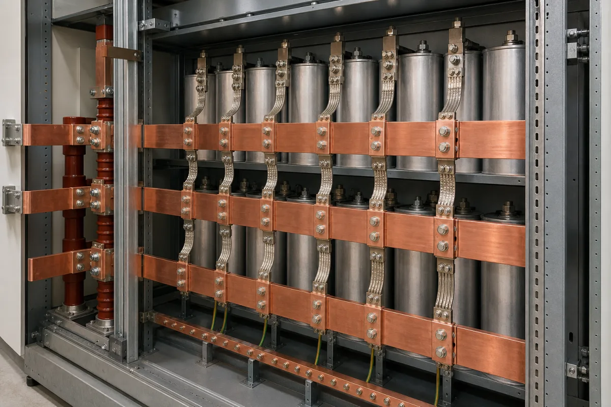
Capacitor bank busbar system: busbars, supports and links inside a power factor correction cabinet
Capacitor bank busbar systems · current margin for harmonics and tolerance, switching inrush, support spacing and short-time withstand, links to each capacitor terminal
A capacitor bank busbar system is the set of three-phase busbars, insulating supports and flexible links that distributes current from the bank's incoming switch to every capacitor unit and step contactor in a power factor correction cabinet. It has to carry more than the capacitors' rated current, survive the inrush each time a step switches in, and hold the bars in place under the plant's short-circuit current. Ask three things first: what current margin the bars are sized for, what short-time withstand current the support arrangement has been tested to, and how each capacitor terminal is connected to the bars.
Busbars, busbar supports and capacitor connection links inside low-voltage power factor correction and capacitor bank cabinets, specified by current margin over capacitor rating, inrush, short-time withstand of the support arrangement and terminal connection. Copper busbars as bar stock, with ampacity by size and temperature rise, copper grade and finish, are covered on the Copper busbar page. Capacitor units on their own, busbar trunking and crane conductor rails are outside this page.
CNFX editorial research · Sources checked October 12, 2026 · 3 sources
Size the bars for the capacitors' overcurrent and switching inrush, not their nameplate current
TDK's PhaseCap Premium power factor correction capacitors, built to IEC 60831-1+2 and UL 810, are rated for overcurrent up to 1.6 × IR including the combined effects of harmonics, overvoltages and capacitance tolerance, and for inrush current up to 300 × IR; capacitance tolerance is −5%/+10%, overvoltage is allowed up to VR + 10% for 8 h daily, and the units are limited to 7500 switching operations per year. [1]
Editorial calculation: if the busbars of a bank are sized to carry every connected unit at TDK's 1.6 × IR limit, a bank whose capacitors total 400 A rated current needs bars, joints and supports for 640 A continuous; the 400 A figure is an assumption for illustration. Ask the bank maker which multiplier it used and whether the bars are rated at the cabinet's internal air temperature; TDK gives the capacitors a maximum ambient of 55 °C with a 24 h mean of 45 °C. [1]
Each PhaseCap Premium unit has a safety terminal limited to a 25 mm² cable cross-section and 80 A, an M12 stud on the bottom of the extruded aluminium can for mounting and grounding, and an overpressure disconnector as its internal safety device. [1] Editorial note: the busbar system therefore ends in links sized to the terminal, not in bars bolted to the capacitor; ask for the link cross-section, material and length for each unit, and for the earthing route from each can's stud.
Give the bank maker the bank kvar and voltage, step sizes, capacitor make and rated current, harmonic content or detuning reactor, prospective short-circuit current and duration at the cabinet, busbar material and finish wanted, cabinet ventilation and ambient temperature, and whether links to each unit are cable or flexible bar.
02
Check the short-time withstand of the busbars at the support spacing used
Busbar supports carry the short-circuit forces, and their tested rating depends on bar size and spacing. Rittal's RiLine busbar support for up to 800 A (60 mm bar centres, bars 15 × 5 to 30 × 10 mm, 690 V operating, 1000 V insulation) is rated under IEC 61439-1:2020 at 250 mm support spacing for a 1 s short-time withstand current of 37.6 kA with 30 × 10 mm bars, 36.0 kA with 30 × 5 mm and 29.0 kA with 20 × 10 mm. [2]
Wöhner's universal busbar support for bars 12 to 30 mm wide and 5 to 10 mm thick lists a rated peak withstand current of up to 73 kA, with 30 × 10 mm bars and two supports 250 mm apart, and a rated short-time withstand current (1.0 s) of up to 34.2 kA, with 1000 V AC insulation voltage and 8 kV impulse voltage. [3]
Editorial calculation: halving the bar thickness from 30 × 10 to 30 × 5 mm lowers Rittal's 1 s rating at 250 mm spacing from 37.6 to 36.0 kA, about 4%, while dropping the width from 30 × 10 to 20 × 10 mm lowers it to 29.0 kA, about 23%. [2] Editorial note: a support catalogue figure is not the rating of the finished bank; ask for the assembly's verified short-circuit rating and the support spacing actually used in the cabinet.
03
Published limits that set the capacitor bank busbar design
Capacitor limits set the continuous and transient current; support ratings set the fault withstand.
Limit
Published value
Effect on the busbar system
Capacitor overcurrent
Up to 1.6 × IR incl. harmonics, overvoltage and tolerance. [1]
1000 V AC rated insulation on both supports. [2][3]
Insulation level for the bank voltage.
04
Busbar data to request with a capacitor bank quotation
Rated current and short-circuit withstand are the two fields to check first, because both are set by the capacitors and the site rather than by the copper.
Field
Published values
Ask the bank maker for
Rated Current (A)
Allow for up to 1.6 × IR of the connected capacitors. [1]
Busbar rating and multiplier used.
Rated Voltage (V AC)
Supports rated up to 690 V AC operating (Rittal). [2]
Bank voltage.
Short-Circuit Withstand (kA)
37.6 kA for 1 s with 30 × 10 mm bars at 250 mm (Rittal); up to 34.2 kA for 1.0 s (Wöhner). [2][3]
Verified assembly rating.
Conductor Material
Copper or aluminium bars; flexible links to units.
Material, size and finish.
Insulation Material
Supports and covers.
Material and flammability.
Degree of Protection
Capacitor units IP20 (IP54 with terminal cap). [1]
1 company lists this product among what they make. Company figures are quoted from each
company's own website; every card states where the relationship came from.
Shanghai Leipold Electric Co.,Ltd.
Manufacturing site to be confirmed for the order
Lists a busbar system category for control cabinets, including busbar adaptors, alongside enclosure fans and terminal blocks; panel busbar components rather than a complete capacitor bank.
Explore company information and manufacturing capabilities, then discuss the scope of your project with a relevant supplier.
Share this page
Compiled and source-reviewed by the CNFX editorial team.
Each manufacturer above links to the page on that company's own website where the product is listed, with the date we checked it. How we source and review
· Page last updated 13 October 2026
Buyer questions
Why are capacitor bank busbars rated above the capacitors' rated current?
Capacitors draw extra current from harmonics, overvoltage and capacitance tolerance; TDK rates its PhaseCap Premium units for up to 1.6 × IR combined. [1]
How large is capacitor switching inrush?
TDK rates PhaseCap Premium units for inrush up to 300 × IR. [1]
What short-circuit current can busbar supports withstand?
Rittal lists 37.6 kA for 1 s with 30 × 10 mm bars and supports 250 mm apart; Wöhner lists up to 34.2 kA for 1.0 s and 73 kA peak for its universal support. [2][3]
Sources and what still needs a direct check
Sources checked 2026-10-12. TDK (EPCOS) states the limits of its own capacitors; Rittal and Wöhner publish tested ratings of their own busbar supports. The verified rating of the finished cabinet governs.