Editorial Technical Reference

Component Insertion Robot

This page explains how Component Insertion Robot is classified within Electrical Equipment Manufacturing. Technical values and manufacturer relationships are research references; confirm the current specification and supplier evidence for each order.

Technical Definition & Core Assembly

Automated robotic system for precise insertion of electrical components into medium voltage switchgear assemblies
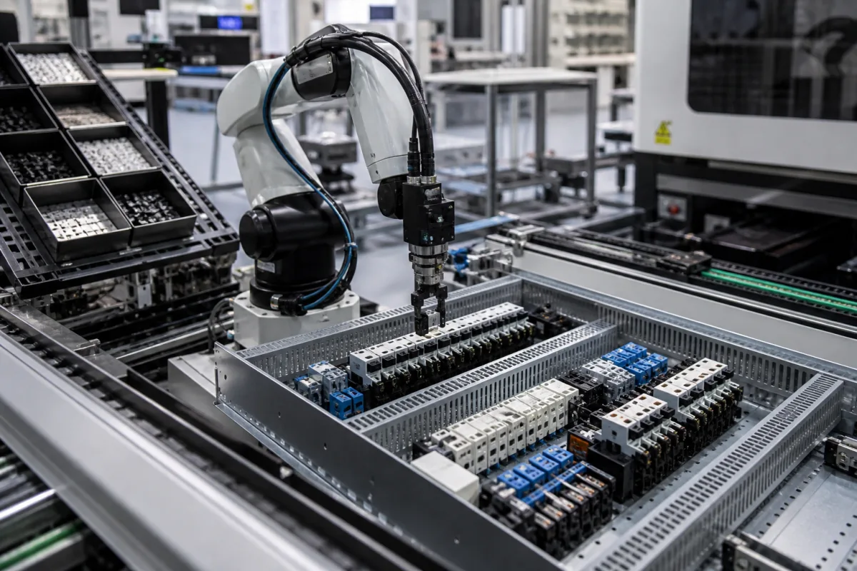
Representative product image. Confirm appearance and specifications with the manufacturer.

Product Specifications

Technical details and manufacturing context for Component Insertion Robot

Definition
The Component Insertion Robot is a specialized robotic system designed for integration into medium voltage switchgear assembly lines. Its primary function is to perform automated, high-precision insertion of critical electrical components—such as circuit breakers, contactors, busbars, and insulation components—into switchgear enclosures. The system ensures consistent placement accuracy, reduces manual labor, and maintains production quality standards in electrical equipment manufacturing.

Constructed with materials including aluminum alloy, stainless steel, industrial-grade plastics, and precision bearings, the robot is built for durability and precision. It operates using a multi-axis articulated arm equipped with precision grippers and vision systems. Components are picked from feeding stations, aligned with pre-programmed insertion points, and inserted with controlled force and positioning. The system relies on CAD/CAM programming and real-time sensor feedback to ensure proper component orientation and seating.

Key parameters include a rated insertion force of 500–2000 N, positioning repeatability of ±0.05 mm (per ISO 9283), insertion speed of 10–30 mm/s, rated payload of 5–15 kg, and 4–6 axes. Operating pressure for pneumatic grippers is 0.5–0.7 MPa (ISO 8573-1), supply voltage is 24 V DC ±10% (IEC 61131-2), and power consumption ranges from 1.5–3.0 kW. The system operates in temperatures from 0–45°C (IEC 60068-2-1/2) and relative humidity of 20–85% non-condensing (IEC 60068-2-78). Ingress protection is IP54–IP65 (IEC 60529). Machine weight is 800–1500 kg, and footprint is approximately 2000×1500×2200 mm.

All values are reference ranges and must be verified with the legal manufacturer or supplier for specific models and applications. Standards listed are for verification purposes only and do not imply certification.
Working Principle
The robot uses a multi-axis articulated arm with precision grippers and vision systems to pick components from feeding stations, align them with pre-programmed insertion points in switchgear assemblies, and insert them with controlled force and positioning. It operates based on CAD/CAM programming and real-time sensor feedback to ensure proper component orientation and seating. The system's control architecture allows for adjustable insertion speed and force to accommodate component fragility. Vision systems verify component presence and alignment before insertion, while force sensors monitor insertion force to prevent damage. The robot's repeatability ensures consistent placement within ±0.05 mm, meeting ISO 9283 standards. The working principle emphasizes precision, adaptability, and integration into automated assembly lines.
Common Materials
Aluminum alloy, Stainless steel, Industrial-grade plastics, Precision bearings
Technical Parameters
ParameterTypical rangeNotes & selection driver
Rated Insertion Force500–2000 NForce range for standard component insertion
Positioning Repeatability±0.05 mmEnsures consistent insertion alignmentISO 9283
Insertion Speed10–30 mm/sAdjustable for component fragility
Rated Payload5–15 kgMaximum component weight
Axis Count4–6Degrees of freedom for complex paths
Operating Pressure0.5–0.7 MPaFor pneumatic gripper actuationISO 8573-1
Supply Voltage24 V DC ±10% VControl and servo powerIEC 61131-2
Power Consumption1.5–3.0 kWTotal system power
Operating Temperature0–45 °CAmbient range for reliable operationIEC 60068-2-1/2
Relative Humidity20–85 %Non-condensingIEC 60068-2-78
Ingress ProtectionIP54–IP65Dust and water resistanceIEC 60529
Machine Weight800–1500 kgIncluding base frame
Footprint (L×W×H)2000×1500×2200 mmApproximate envelope

Ranges are indicative industry figures for RFQ preparation, not a supplier commitment. Confirm every value and standard with the legal manufacturer before ordering.

Components / BOM
  • Robotic Arm
    Multi-axis articulated arm providing precise movement and positioning
  • End Effector/Gripper
    Specialized tooling for securely holding and manipulating electrical components
  • Vision System
    Camera and sensors for component recognition and alignment verification
  • Control System
    PLC and motion controllers for programming and operation management
  • Force Sensors
    Watch the insertion force so a mis-aligned component is not pushed home and broken.

Applied To / Applications

This component is essential for the following industrial systems and equipment:

Industrial Ecosystem & Supply Chain Structure

Complementary Systems
Downstream Applications
Specialized Tooling

Application Fit & Sizing Matrix

Operational Limits
pressure: Atmospheric (no pressure requirements for insertion process)
other spec: Component size range: 5mm to 150mm, Insertion force: 0.5N to 50N, Positioning accuracy: ±0.1mm
temperature: 15°C to 40°C (operating environment)
Media Compatibility
✓ PCB-mounted connectors ✓ Terminal blocks ✓ Busbar insulators
Unsuitable: Corrosive or explosive atmospheres (requires clean, controlled environment)
Sizing Data Required
  • Component dimensions and weight
  • Production cycle time requirements
  • Switchgear panel size and accessibility constraints

Reliability & Engineering Risk Analysis

Failure Mode & Root Cause
Misalignment of insertion mechanism
Cause: Wear in linear guides or ball screws due to inadequate lubrication and particulate contamination, leading to positional drift and insertion errors.
Gripper actuator failure
Cause: Fatigue or overheating of pneumatic or electric actuators from excessive cycle rates, improper pressure settings, or lack of preventive maintenance, resulting in dropped or misoriented components.
Maintenance Indicators
  • Audible grinding or squealing from linear motion components during operation
  • Visible misalignment or deviation in component placement accuracy beyond specified tolerances
Engineering Tips
  • Implement a strict lubrication and contamination control regimen for all linear motion components, using manufacturer-recommended lubricants and scheduled cleaning intervals.
  • Conduct regular calibration and alignment checks using laser alignment tools or precision gauges to ensure insertion accuracy and prevent premature wear.

Indicative industry ranges for design and RFQ preparation. Confirm the exact figures and applicable standard with the manufacturer before specifying.

Compliance & Manufacturing Standards

Applicable Standards
ISO 10218-1:2011 (Robots and robotic devices - Safety requirements - Part 1: Industrial robots) ANSI/RIA R15.06-2012 (Industrial Robots and Robot Systems - Safety Requirements) CE Marking (EU Machinery Directive 2006/42/EC)

Quoted from the published standard.

Manufacturing Precision
  • Positioning repeatability: +/-0.05mm
  • Force control accuracy: +/-2% of full scale
Quality Inspection
  • Laser interferometer calibration test
  • Functional safety performance test (PL/SIL verification)

Manufacturers of Component Insertion Robot

Manufacturer profiles associated with Component Insertion Robot.

Sourcing Component Insertion Robot from China?
Tell us your specification and target quantity — we will match it against manufacturer records and come back with the factories that fit.
Request manufacturers We manufacture this

Manufacturer listings support early research and capability understanding. They are not certification, ranking, or transaction guarantees.

Technical documentation
Request current drawings, revision history, and a signed specification sheet.
Manufacturing capability
Verify equipment lists, process limits, capacity, and representative production evidence.
Inspection readiness
Confirm test methods, calibrated equipment, sampling plans, and traceable reports.
Supplier transparency
Check the legal entity, factory address, ownership, certifications, and direct contacts.

CNFX does not score or rank suppliers. Buyers must verify all claims and documents with the legal manufacturer before ordering.

Supply Chain Compatible Machinery & Devices

Medium Voltage Switchgear Assembly Line

Automated production system for assembling medium voltage electrical switchgear.

Explore Specs →
Motor Terminal Block

A motor terminal block is a standardized electrical component that provides secure, insulated connection points for motor winding leads.

Explore Specs →
PLC Control System

A digital industrial computer control system that monitors inputs, makes decisions based on a custom program, and controls outputs to automate industrial processes.

Explore Specs →
Control Panel

A centralized interface for monitoring and controlling industrial equipment and processes

Explore Specs →

Frequently Asked Questions

What is the positioning repeatability of the Component Insertion Robot?

The positioning repeatability is ±0.05 mm, as listed in the reference parameters. This value is per ISO 9283 and should be verified with the manufacturer for the specific model.

What is the operating temperature range for this robot?

The operating temperature range is 0–45°C, as per IEC 60068-2-1/2. This is a reference range; confirm with the supplier for your application.

What standards are referenced for the robot's performance?

Standards referenced include ISO 9283 for positioning repeatability, ISO 8573-1 for operating pressure, IEC 61131-2 for supply voltage, IEC 60068-2-1/2 for temperature, IEC 60068-2-78 for humidity, and IEC 60529 for ingress protection. These are verification references, not certifications.

Can the robot handle different component sizes?

The robot is designed for components within its rated payload of 5–15 kg and insertion force range of 500–2000 N. Specific component sizes and geometries should be evaluated with the manufacturer to ensure compatibility.

Data Basis

Editorial classification, named public sources where available, and source-reviewed manufacturer records.

Preliminary Technical Classification
This page supports structured research, RFQ preparation, and supplier evaluation. It does not replace buyer-led supplier qualification, standards review, or technical approval.
Buyer enquiry

Request manufacturing insight for Component Insertion Robot

Ask for use case, specification boundaries, supplier type, and RFQ preparation information for this product.

Where it goes
Straight to the CNFX editorial desk, and to the manufacturer if this product is linked to a claimed profile. Nothing is broadcast to a supplier list.
Your details stay here
We do not sell or rent enquiry data, and we do not add you to a mailing list. Used only to answer this request.
No commission, no middleman
CNFX is a directory. We take no cut of any order and never negotiate on a supplier's behalf.
What we don't claim
A listing is not an endorsement. Qualify every supplier and verify every figure yourself before ordering.

Your business information is used only to process this request.

Thank you! Your message has been sent. We'll respond within 1–3 business days.
Sorry, we couldn't send your message. Please try again, or email us at contact@cnfx.com.

Need to Manufacture Component Insertion Robot?

Compare manufacturer profiles with relevant product and process capability.

Previous Product
Circuit Breakers / Fuses
Next Product
Conductor Rails
Get QuotesChat