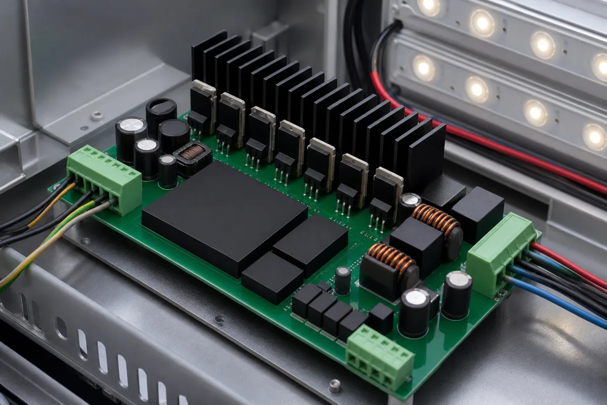
DMX512 LED controller/driver (constant-voltage PWM decoder)
Low-voltage LED controller/driver boards · DMX512 decoding, PWM frequency and bit depth, per-channel current on 12–24 V DC
A DMX512 LED controller/driver, also sold as a DMX decoder or PWM dimmer, is a low-voltage board that sits between a constant-voltage DC power supply and LED strips or modules. It reads lighting levels from a DMX512 network and switches each output channel with pulse-width modulation, so one unit can dim or colour-mix red, green, blue and white strips. Ask three things first: how it connects to the DMX network and how many addresses it takes, what PWM frequency and resolution it outputs, and how much current each channel and the board can carry at your supply voltage.
Low-voltage (12–24 V DC class) multi-channel LED controller/driver boards and DMX512 decoders that convert DMX512 control data into PWM outputs for constant-voltage LED strips and modules, specified by DMX interface, address setting, PWM frequency and bit depth, channel current and power. Mains-powered AC-DC constant-current and constant-voltage LED drivers (control gear) are covered on the LED driver page. Lighting consoles, wireless controllers, driver ICs and complete luminaires are outside this page.
CNFX editorial research · Sources checked October 12, 2026 · 3 sources
Texas Instruments' Analog Applications Journal article on DMX512 describes a controller transmitting packets of asynchronous serial data at 250 kbps. A packet starts with a break and a mark-after-break, followed by time slots of one start bit, eight data bits and two stop bits; a packet has at most 513 slots, 512 of them data, and the first slot, the start code, gives the type of data. [1] Editorial calculation: 11 bits at 250 kbps take 44 µs per slot, so a full 513-slot packet takes about 22.6 ms plus break and mark, a ceiling of about 44 full packets per second.
The same article states that DMX512-A specifies EIA-485 as the physical layer, allowing up to 32 unit loads and a bus length of up to 1,200 m, on twisted pair of 120 Ω RS-485 cable or 100 Ω CAT5 cable with a matching termination resistor at the end of the bus. DMX512-A recommends earth-grounded transmitter ports and isolated receiver ports to avoid ground loops, and responders that return status data must have isolated transmit and receive ports. [1]
On the decoder side, Leynew's LN-DMXTCON-4CH-LV uses RJ45 DMX input and output connectors and a ten-position coding switch: nine binary switches set the DMX start address and the tenth selects test functions. [2] AUTLED's LC-035-004 RGBW decoder sets its DMX address on a 4-digit display and lets 1 to 4 DMX addresses drive its four outputs, from all channels on one address to one address per channel. [3]
Editorial note: ask whether the board's DMX receiver is isolated, which connector it uses, how many addresses it occupies in each mode, and whether it supports RDM if status feedback is needed.
Send the DMX network details (controller, cable type, connector, number of units on the line), required addresses per unit, LED load per channel (type, voltage, watts), supply voltage, PWM frequency and bit depth needed for cameras or low-level dimming, enclosure and mounting, and ambient temperature.
02
Set PWM frequency, resolution and channel load
The two published decoders differ in PWM output. Leynew lists a controller output frequency of 980 Hz for its 4-channel unit. [2] AUTLED's 4-channel unit lets the PWM frequency be set from 500 Hz to 30 kHz in 1,000 Hz steps (factory default 1 kHz), PWM resolution of 8 or 16 bit (default 16 bit), and a dimming-curve gamma from 0.1 to 9.9 (default 1.5). [3] Editorial calculation: 8 bit gives 256 levels and 16 bit 65,536 levels.
Channel current sets the LED load. Leynew rates its decoder at 4 A per channel with output power below 192 W at 12 V and below 384 W at 24 V, on a DC 12–24 V supply, working temperature −20 to 60 °C and static consumption below 1 W. [2] AUTLED rates its board at 5 A per channel and 4 × 60 W at 12 V or 4 × 120 W at 24 V, for wire up to 2.5 mm², and states that the product must be worked with a DC constant-voltage power supply. [3] Editorial calculation: 4 channels × 4 A × 12 V = 192 W and × 24 V = 384 W, matching Leynew's totals; 5 A × 12 V = 60 W per channel, matching AUTLED's figure.
AUTLED lists its four PWM output channels with a shared anode, so the LED strip wiring must match that arrangement. [3] Editorial note: choose the power supply for the sum of the connected loads, not the board's maximum, and allow ventilation; AUTLED's manual asks for installation in a well-ventilated area. [3]
03
Compare two published 4-channel decoders
Values below are as each maker publishes them; confirm the current revision with the supplier.
Current per channel; shared-anode or shared-cathode wiring.
Terminals
Supply and load connections up to 2.5 mm² in one unit. [3]
Wire size and terminal type.
Enclosure and heat sink
Removes heat from the output switches.
Housing, IP rating, ventilation.
05
Quote the decoder on supply, channel current and PWM
Power factor, line and load regulation and ripple belong to the DC supply rather than the decoder; the table says so field by field, with values cited where a source gives them.
Field
What it means and published values
Ask the supplier for
Input voltage (V AC)
For DMX decoders the input is DC: 12–24 V in both units reviewed. [2][3]
Supply range; AC input only if a built-in supply is offered.
Output voltage (V DC)
Equals the constant-voltage supply in these designs. [3]
Strip voltage supported.
Output current (mA)
4,000 mA or 5,000 mA per channel in the units reviewed. [2][3]
Per channel and total.
Output power (W)
192–384 W or 4 × 60–120 W depending on voltage. [2][3]
Explore company information and manufacturing capabilities, then discuss the scope of your project with a relevant supplier.
Share this page
Compiled and source-reviewed by the CNFX editorial team.
Each manufacturer above links to the page on that company's own website where the product is listed, with the date we checked it. How we source and review
· Page last updated 13 October 2026
Buyer questions
How fast is DMX512?
Texas Instruments describes DMX512 packets at 250 kbps with up to 513 slots, 512 of them data. [1]
What PWM frequency do DMX LED decoders use?
It varies by model: one 4-channel decoder lists 980 Hz; another lets it be set from 500 Hz to 30 kHz. [2][3]
Does a DMX decoder replace the LED power supply?
No. AUTLED states its decoder must be worked with a DC constant-voltage power supply. [3]
Sources and what still needs a direct check
Sources checked 2026-10-12. Texas Instruments' journal article summarises the DMX512-A protocol and physical layer; Leynew and AUTLED are LED controller sellers publishing datasheets and manuals for their own decoders.