Editorial Technical Reference

Heat Management System

This page explains how Heat Management System is classified within Electrical Equipment Manufacturing. Technical values and manufacturer relationships are research references; confirm the current specification and supplier evidence for each order.

Technical Definition & Core Assembly

A subsystem in programmable lighting systems that monitors, regulates, and dissipates heat from lighting components to ensure performance and longevity.
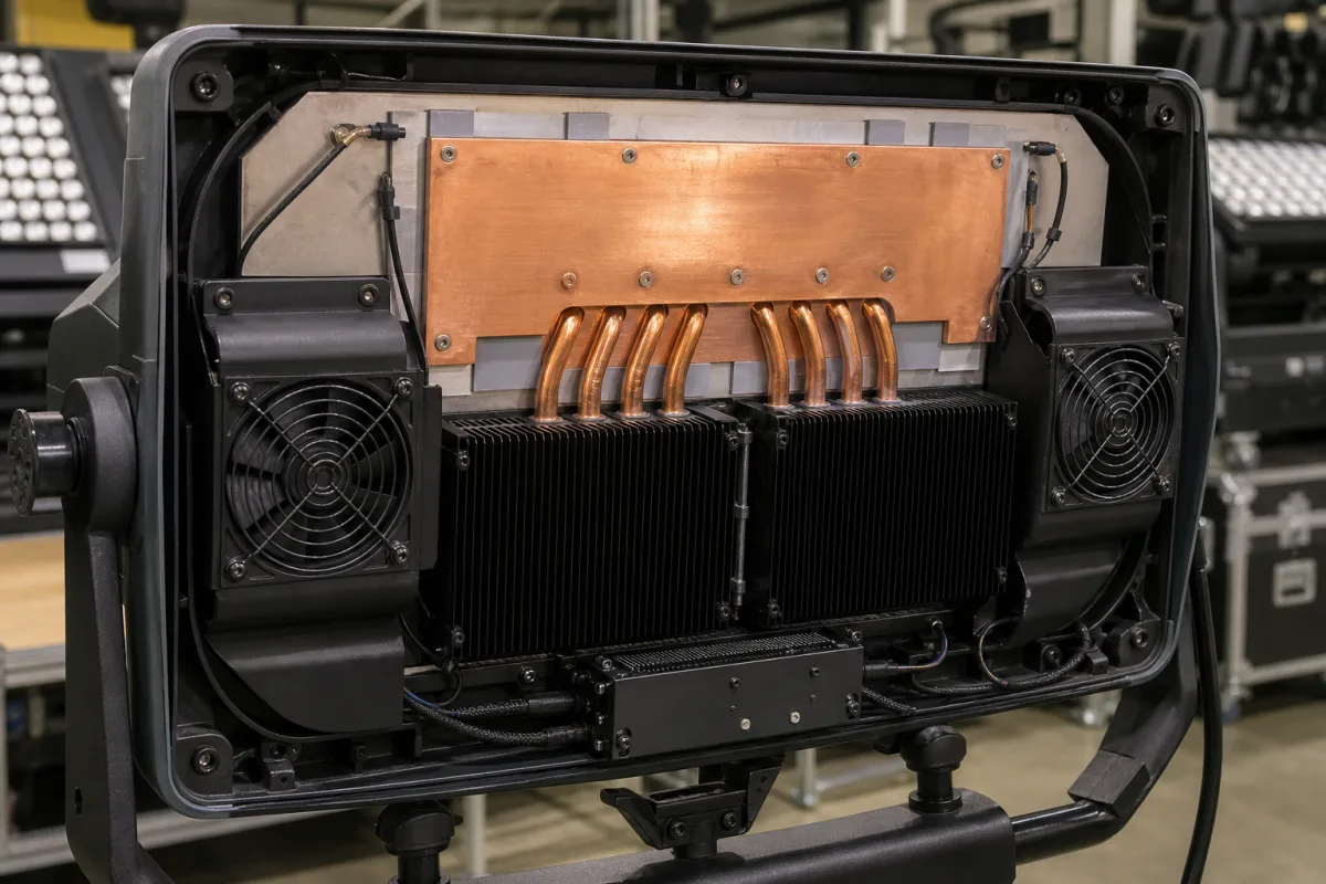
Representative product image. Confirm appearance and specifications with the manufacturer.

Product Specifications

Technical details and manufacturing context for Heat Management System

Definition
The Heat Management System is an integral component of Programmable Lighting Systems that actively controls thermal conditions within lighting fixtures. It prevents overheating of LEDs, drivers, and control electronics by employing thermal sensors, heat sinks, and cooling mechanisms. This system maintains temperature within safe operating ranges, preventing premature failure, color shifting, and efficiency degradation while enabling consistent lighting performance across various environmental conditions. The system operates through thermal sensors that monitor temperature at critical points within lighting fixtures. When temperatures exceed predetermined thresholds, the system activates cooling mechanisms such as passive heat dissipation through aluminum heat sinks or active cooling via fans. In programmable systems, it can adjust lighting intensity or duty cycles to reduce heat generation while maintaining desired illumination levels. The system is designed for integration into lighting fixtures and supports various cooling capacities, operating temperature ranges, and coolant flow rates depending on the application. It may include liquid-cooled options with specified pressure drops and thermal resistance values. Input voltage is typically 24 V DC with a tolerance of ±10%. Power consumption ranges from 5 to 50 W, including fans, pumps, and control electronics. The system is available with IP ratings from IP54 to IP65, suitable for indoor and outdoor use. Noise levels range from 20 to 40 dB(A), and weight varies from 0.5 to 5 kg. Dimensions range from 100×50×30 mm to 300×150×100 mm. Materials commonly used include aluminum alloy (6061–6063) per ASTM B221, thermal interface materials, and copper heat pipes. For liquid-cooled systems, coolant flow rate ranges from 0.5 to 5 L/min, and pressure drop from 0.1 to 0.5 bar. Thermal resistance ranges from 0.05 to 0.5 K/W. These values are reference ranges; actual specifications must be confirmed with the manufacturer for the specific model and application. The system is a component, not a standalone product, and its performance depends on proper integration and environmental conditions.
Working Principle
The system uses thermal sensors to monitor temperatures at critical points in the lighting fixture. When temperatures exceed set thresholds, it activates cooling mechanisms: passive heat dissipation via aluminum heat sinks or active cooling via fans. In programmable systems, it can also adjust lighting intensity or duty cycles to reduce heat generation while maintaining desired illumination. This ensures components stay within safe operating ranges, preventing overheating and degradation.
Common Materials
Aluminum alloy, Thermal interface material, Copper heat pipes
Technical Parameters
ParameterTypical rangeNotes & selection driver
Cooling Capacity50–500 WDetermines maximum heat dissipation for LED modules
Operating Temperature Range-40–85 °CSurvival range; performance may derate at extremes
Coolant Flow Rate0.5–5 L/minRequired for liquid-cooled systems
Pressure Drop0.1–0.5 barAffects pump sizing and system efficiency
Thermal Resistance0.05–0.5 K/WLower is better for heat transfer
Input Voltage24 ±10% V DCTypical for LED lighting systems
Power Consumption5–50 WIncludes fans, pumps, and control electronics
IP RatingIP54–IP65Higher rating for outdoor or dusty environmentsIEC 60529
Noise Level20–40 dB(A)Important for indoor applications
Weight0.5–5 kgAffects mounting and structural support
Dimensions (L×W×H)100×50×30–300×150×100 mmEnvelope size for integration
MaterialAluminum 6061–6063Corrosion resistance and thermal conductivityASTM B221

Ranges are indicative industry figures for RFQ preparation, not a supplier commitment. Confirm every value and standard with the legal manufacturer before ordering.

Components / BOM
  • Thermal Sensor Array
    Monitors temperature at critical points within lighting fixtures
    Material: Semiconductor materials
  • Heat Sink Part
    Passively dissipates heat through extended surface area
    Material: Aluminum alloy
  • Cooling Fan
    Actively moves air to enhance heat dissipation
    Material: Plastic housing with copper windings
  • Thermal Interface Material Part
    Improves heat transfer between components and heat sink
    Material: Thermal paste or pad

Applied To / Applications

This component is essential for the following industrial systems and equipment:

Industrial Ecosystem & Supply Chain Structure

Complementary Systems
Downstream Applications
Specialized Tooling

Application Fit & Sizing Matrix

Operational Limits
pressure: Atmospheric pressure operation only (0-1 bar gauge), no pressurized systems
flow rate: Forced air cooling: 10-100 CFM, liquid cooling: 0.5-5 L/min (if applicable)
temperature: Operating range: -20°C to 85°C ambient, component surface monitoring up to 125°C
thermal load: Dissipation capacity: 50-500W per lighting module
Media Compatibility
✓ LED lighting arrays ✓ Electronic driver components ✓ Enclosed fixture interiors
Unsuitable: High-vibration industrial environments (e.g., heavy machinery adjacent)
Sizing Data Required
  • Total thermal load (W)
  • Maximum ambient temperature (°C)
  • Available space/volume for heat dissipation (m³)

Reliability & Engineering Risk Analysis

Failure Mode & Root Cause
Corrosion-induced leakage
Cause: Chemical attack from coolant additives, dissolved oxygen, or improper pH levels leading to pitting and perforation of heat exchanger tubes or piping.
Fouling and scaling
Cause: Accumulation of mineral deposits, biological growth, or particulate matter on heat transfer surfaces, reducing thermal efficiency and increasing pressure drop.
Maintenance Indicators
  • Unusual temperature fluctuations or inability to maintain setpoint despite normal operation
  • Audible water hammer or gurgling noises indicating air entrapment or flow restriction
Engineering Tips
  • Implement regular water treatment monitoring and chemical analysis to maintain proper pH, conductivity, and biocide levels
  • Install magnetic or electronic descaling devices upstream of critical components to reduce mineral deposition without chemical additives

Indicative industry ranges for design and RFQ preparation. Confirm the exact figures and applicable standard with the manufacturer before specifying.

Compliance & Manufacturing Standards

Applicable Standards
ANSI/ASHRAE 90.1 - Energy Standard for Buildings Except Low-Rise Residential Buildings CE Marking - EU Directive 2014/35/EU (Low Voltage Directive)

Quoted from the published standard.

Manufacturing Precision
  • Flatness of Heat Exchanger Plates: +/- 0.1mm
  • Thermal Expansion Joint Clearance: +/- 0.5mm
Quality Inspection
  • Pressure Leak Test (Hydrostatic/Pneumatic)
  • Thermal Performance Test (Heat Transfer Efficiency Measurement)

Manufacturers of Heat Management System

Manufacturer profiles associated with Heat Management System.

Sourcing Heat Management System from China?
Tell us your specification and target quantity — we will match it against manufacturer records and come back with the factories that fit.
Request manufacturers We manufacture this

Manufacturer listings support early research and capability understanding. They are not certification, ranking, or transaction guarantees.

Technical documentation
Request current drawings, revision history, and a signed specification sheet.
Manufacturing capability
Verify equipment lists, process limits, capacity, and representative production evidence.
Inspection readiness
Confirm test methods, calibrated equipment, sampling plans, and traceable reports.
Supplier transparency
Check the legal entity, factory address, ownership, certifications, and direct contacts.

CNFX does not score or rank suppliers. Buyers must verify all claims and documents with the legal manufacturer before ordering.

Supply Chain Compatible Machinery & Devices

Medium Voltage Switchgear Assembly Line

Automated production system for assembling medium voltage electrical switchgear.

Explore Specs →
Motor Terminal Block

A motor terminal block is a standardized electrical component that provides secure, insulated connection points for motor winding leads.

Explore Specs →
PLC Control System

A digital industrial computer control system that monitors inputs, makes decisions based on a custom program, and controls outputs to automate industrial processes.

Explore Specs →
Control Panel

A centralized interface for monitoring and controlling industrial equipment and processes

Explore Specs →

Frequently Asked Questions

What is the typical input voltage for this system?

The typical input voltage is 24 V DC with a tolerance of ±10%. However, always verify the exact requirement for your specific model and application with the manufacturer.

What cooling methods are used?

The system uses passive cooling via aluminum heat sinks and active cooling via fans. For liquid-cooled versions, it may use coolant flow with specified flow rates and pressure drops.

What are the operating temperature limits?

The operating temperature range is -40°C to 85°C. Performance may derate at extreme temperatures. Confirm the exact limits for your model.

Is this system suitable for outdoor use?

The system is available with IP ratings from IP54 to IP65, which indicate protection against dust and water. Higher ratings are suitable for outdoor or dusty environments. Verify the IP rating for your specific model.

Data Basis

Editorial classification, named public sources where available, and source-reviewed manufacturer records.

Preliminary Technical Classification
This page supports structured research, RFQ preparation, and supplier evaluation. It does not replace buyer-led supplier qualification, standards review, or technical approval.
Buyer enquiry

Request manufacturing insight for Heat Management System

Ask for use case, specification boundaries, supplier type, and RFQ preparation information for this product.

Where it goes
Straight to the CNFX editorial desk, and to the manufacturer if this product is linked to a claimed profile. Nothing is broadcast to a supplier list.
Your details stay here
We do not sell or rent enquiry data, and we do not add you to a mailing list. Used only to answer this request.
No commission, no middleman
CNFX is a directory. We take no cut of any order and never negotiate on a supplier's behalf.
What we don't claim
A listing is not an endorsement. Qualify every supplier and verify every figure yourself before ordering.

Your business information is used only to process this request.

Thank you! Your message has been sent. We'll respond within 1–3 business days.
Sorry, we couldn't send your message. Please try again, or email us at contact@cnfx.com.

Need to Manufacture Heat Management System?

Compare manufacturer profiles with relevant product and process capability.

Previous Product
Grid Monitoring Device
Next Product
Heating Element Module
Get QuotesChat