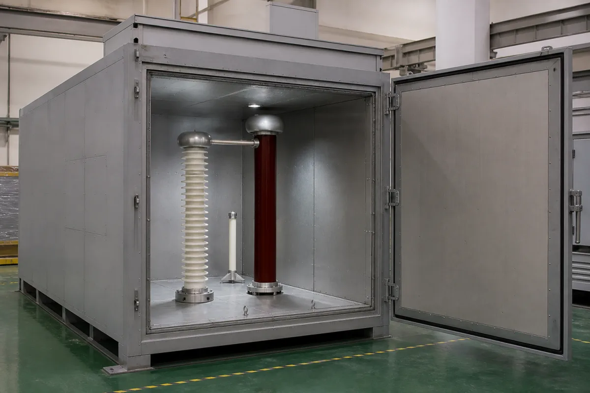
High-voltage test chamber for switchgear components: the walk-in steel cell with interlocked door and automatic earthing that encloses an interrupter or insulator under test
Walk-in steel test cells for switchgear components · door interlock, automatic earthing, 1 in per 7.5 kV spacing inside, vacuum interrupters at 42/48 kV
A component test chamber is a small earthed steel room with a door: the interrupter, insulator or bushing goes in, the door shuts, and only then can the high voltage come on. A buyer has to settle three things: what stops anyone reaching a live part (interlocks, earthing, warning lights), how much space the internal electrodes and test object need from the walls, and which test voltages the components that will go through it are rated for.
Enclosed, earthed walk-in or cabinet-size test cells for withstand testing of individual medium-voltage switchgear components — vacuum interrupters, post and support insulators, bushings, cast-resin parts — with their door interlocks, automatic and manual earthing, warning lights, internal clearances, viewing windows, and lead-outs for measurement. Screened rooms for final withstand and partial-discharge tests on complete assembled switchgear panels are covered on the Final test chamber for medium-voltage switchgear panels page; the hipot testers and AC test sets that energise a chamber on the Dielectric strength (hipot) tester and High-voltage test transformer pages; DC test sets on the High-voltage generator for DC withstand page; regulators on the Voltage control unit for dielectric strength testers page. RF-shielded EMC chambers are covered on the EMI shielded enclosures and EMC test chambers page, and the interrupter pole as a breaker component on the Vacuum interrupter pole assembly page.
CNFX editorial research · Sources checked October 13, 2026 · 3 sources
Door interlock, automatic earthing and a flashing light: NIST's rules for an enclosure above 1,000 V
NIST's EEEL safety rules (revision of 2008) define high voltage as anything above 1,000 V rms or dc with current capability above 2 mA ac or 3 mA dc. All conductors that may carry it should be confined in grounded or insulated enclosures, and bare conductors at high voltage must sit inside grounded safety enclosures with working interlocks, so that contact is impossible without tripping the interlock except by deliberate breach of the enclosure. [1]
The rules define an interlock as a circuit that prevents energising the supply until all access doors are closed and de-energises it immediately if a door is opened, and add that this does not necessarily ensure full discharge of stored energy. That is why the same document requires a grounding stick on the high-voltage terminal before anyone touches the circuit, left there until it is about to be re-energised, and makes automatic grounding mandatory for one-person and unattended operation. [1]
A warning light, preferably flashing and ideally switched by energising the apparatus, must be on while high voltage is present, and where the area opens directly from a hallway the rules require the light, a DANGER HIGH VOLTAGE sign, a safety interlock and a locked door. All interlocks are to be tested at Division safety reviews. [1]
Spellman's reproduction of IEEE Std 510-1983 adds requirements on the supply side: a single obvious emergency-off control, an indicator that the high-voltage output is enabled, and external interlock connections that switch the source off when opened, for barrier switches or a foot or hand safety switch. It recommends automatic grounding devices that apply a visible ground after de-energising, and says leads leaving the test area should run in grounded metallic sheaths to grounded enclosures, with meters that have accessible terminals placed in a metal compartment with a viewing window. [2]
Ask how the door interlock is wired into the test set's external interlock input, whether earthing is automatic on opening, which warning lights are fitted, and how measuring leads leave the cell.
02
1 in per 7,500 V: clearance from the electrodes and test object to the earthed walls, and creepage on supports
The spacing rule in Spellman's IEEE Std 510 excerpts is a single ratio: every object at ground potential at least 1 in (25.4 mm) from any exposed high-voltage point for every 7,500 V, so 50 kV needs at least 6.7 in (171 mm). Insulators in contact with high-voltage points get the same allowance as creepage, 1 in per 7,500 V. [2]
Editorial calculation: the ratio is about 3.4 mm per kV, applied here to the stated test voltages; the 75 kV row applies the same ratio to a peak impulse value, which the excerpt does not address separately. These are minimum spacings to grounded objects for safety, not the electrical design clearance of the electrodes against flashover in the cell.
Outside a permanent enclosure, NIST's rules call for a temporary grounded safety fence or ropes at 1 m or more from the exposed conductor, two-person operation and the voltage switched from outside the test area. [1]
Give the highest test voltage, its waveform and the size of the largest test object, so the cell's inside dimensions leave the spacing above around the electrodes and object.
03
What goes inside: a 12 kV vacuum interrupter rated 42/48 kV for one minute and 75 kV impulse, with a 9 mm gap
Ghorit's TD-12/630-25 (2D76) vacuum interrupter for indoor circuit breakers lists a rated voltage of 12 kV, a short-time power-frequency withstand of 42/48 kV for one minute and a rated lightning impulse withstand of 75 kV peak. The mechanical data for a switch fitted with it give a clearance between open contacts of 9 ± 1 mm. [3]
The same data sheet notes that the rated insulation values require external insulation such as SF6, oil or solid dielectric material. [3] A bare interrupter withstand-tested in the air of a test cell is therefore not under the external insulation its ratings assume; the test arrangement and voltage have to be agreed with the interrupter maker.
Other values on the data sheet set what the cell has to hold mechanically and what is measured after the test, not the voltage: 630 A rated current, contact closed force due to bellows and atmosphere of 110 ± 30 N, and circuit resistance below 20 µΩ at minimum rated contact force. [3]
List each component type to be tested with its rated voltage, one-minute and impulse test values, and how it is to be insulated externally during the test.
04
Data for a component high-voltage test chamber
Paste it into your enquiry below or into an email to a maker, then replace every bracket.
Test objects: [vacuum interrupters, insulators, bushings, cast-resin parts; largest size and weight]
Voltages: [power-frequency kV and duration; impulse kV peak; DC if used]
Supply: [test set or transformer inside or outside the cell; feed-through]
Inside size: [W × D × H; spacing to walls around electrodes and object]
Safety: [door interlock to test-set interlock input; automatic earthing; warning light; emergency off]
Measurement: [lead-outs in earthed conduit; viewing window; instrument compartment]
Operation: [one-person or two-person; access from hallway or from a closed laboratory]
Explore company information and manufacturing capabilities, then discuss the scope of your project with a relevant supplier.
Share this page
Compiled and source-reviewed by the CNFX editorial team.
Each manufacturer above links to the page on that company's own website where the product is listed, with the date we checked it. How we source and review
· Page last updated 13 October 2026
Buyer questions
What does a door interlock on a high-voltage test chamber have to do?
NIST's rules say it must prevent energising until all access doors are closed and de-energise immediately if a door opens, and note that it does not by itself ensure stored energy is discharged. [1]
How much spacing is needed around high-voltage parts inside a test cell?
Spellman's IEEE Std 510 excerpts give 1 in (25.4 mm) to grounded objects per 7,500 V, so 50 kV needs at least 6.7 in (171 mm). [2]
What test voltages does a 12 kV vacuum interrupter carry?
Ghorit's TD-12/630-25 lists 42/48 kV power-frequency for one minute and 75 kV peak lightning impulse, with ratings that assume external insulation such as SF6, oil or solid dielectric. [3]
Is automatic earthing required in a high-voltage test area?
NIST makes automatic grounding mandatory for one-person and unattended operation and strongly encourages it for two-person operation. [1]
Sources and what still needs a direct check
Sources checked 2026-10-13. NIST's EEEL safety rules for moderate and high voltages (interlocks, grounding, warning lights, fencing), Spellman High Voltage's reproduction of IEEE Std 510-1983 practices (supply interlocks, lead-outs, spacing), and Ghorit Electrical's 12 kV vacuum interrupter data sheet (test voltages and gap of a component tested in such a cell).