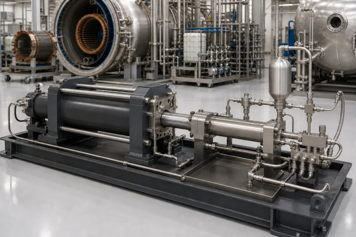
Pressure intensifier: the piston booster unit, sized by area ratio and outlet flow
Piston pressure booster · area ratio, outlet flow at each ratio, single-stroke or reciprocating, oil or gas
A pressure intensifier, also sold as a pressure booster, is a piston device in which a supply acting on a large area drives a smaller piston, so the fluid on the small side leaves at a higher pressure in proportion to the area ratio. It is bought as a separate unit or skid and placed where only one part of a circuit needs the high pressure. Settle three things with the maker: the ratio and the outlet pressure it must reach from the supply you have, how much high-pressure flow or volume you need at that ratio, and whether the medium is oil, water or a gas.
Piston-type pressure intensifiers and boosters as units or skids: oil-to-oil and air-to-oil hydraulic intensifiers and air-driven gas boosters that raise pressure by an area ratio. The impregnation vessel and its vacuum, pressure and resin-transfer system as a whole are covered on the Vacuum pressure impregnation (VPI) chamber page, and electro-hydraulic pressure control assemblies for presses (proportional valves, transmitters, accumulators) on the Hydraulic pressure control system for presses page; stand-alone pumps, compressors and accumulators are outside this page.
CNFX editorial research · Sources checked October 12, 2026 · 5 sources
Outlet pressure comes from the piston area ratio and the supply pressure
Hänchen describes the principle for its hydraulic intensifiers: the primary pressure p1 acts on area A1 with effective diameter D1, and the resulting force generates the secondary pressure p2 on the smaller area with effective diameter D2, in proportion to the area ratio. Its design table pairs D1 and D2 with a transmission ratio and the primary pressure needed for each rated secondary pressure; the dynamic limits, it notes, depend on stroke volume and pressure amplitude and must be calculated for the application. [1]
Editorial calculation: (125 ÷ 30)² = 17.36, matching Hänchen's ratio for that pair, and 230 bar × 17.36 = 3,993 bar, close to the 4,000 bar rating. [1]
Power & Motion's hydraulics handbook chapter gives the same arithmetic for an air-over-oil intensifier: a 5 in. air piston against a 1 in. oil piston is a 25:1 area ratio, so 80 psi of air produces 2,000 psi on the oil. A 6 in. air cylinder driving a 1.5 in. hydraulic cylinder gives 16:1, and 80 psi air then yields approximately 1,300 psi. [4]
miniBOOSTER writes the outlet pressure of its HC2 inline unit as P_H = (P_IN − P_RETURN) × intensification factor, with inlet pressure 20–207 bar and return pressure kept as low as possible; outlet pressure is adjusted by varying the supplied pressure. [2] Because the return-line pressure is subtracted before multiplying, back-pressure in the tank line costs outlet pressure at the full ratio.
Rated p2 (bar)
D1 / D2 (mm)
Transmission ratio
p1 needed (bar)
Dynamics
630
100 / 60
2.78
227
up to 20 Hz
630
160 / 100
2.56
246
up to 20 Hz
1,600
125 / 50
6.25
256
up to 10 Hz
1,600
160 / 60
7.11
225
up to 10 Hz
4,000
125 / 30
17.36
230
static
4,000
160 / 40
16.00
250
static
State the supply pressure available at the intensifier inlet, the return or exhaust back-pressure, the outlet pressure needed and its tolerance, the high-pressure medium, the flow or volume per cycle, how long pressure must be held, and the connection and mounting arrangement.
02
Higher ratios deliver less outlet flow, so choose the ratio against the flow you need
miniBOOSTER's flow table for the HC2 shows the trade-off directly: maximum intensified outlet flow is 3.5 l/min at factor 1.2, 2.0 l/min at 4.0, 0.9 l/min at 9.0 and 0.5 l/min at 16.0, across 15 factors in the series, while outlet pressure is capped at 800 bar whatever the factor. [2]
Editorial calculation: at factor 9.0 with zero return pressure, an inlet above 800 ÷ 9 = 88.9 bar would ask for more than the 800 bar cap, so a high-ratio HC2 is meant for low supply pressures; at factor 4.0, the 800 bar cap is reached at a 200 bar inlet. [2]
ScanWill's MP-2000 in-line intensifier, sold by IC Fluid Power, takes supply up to 200 bar and is offered in four ratios: 7.0 for 1,400 bar, 10.0 for 2,000 bar, 13.0 for 2,600 bar and 16.0 for 3,000 bar, with maximum inlet flow falling from 13 l/min at ratio 7.0 to 10 l/min at 13.0 and 16.0. The ratio-16 version is limited to 188 bar supply. The MP-2100 variant takes up to 15 l/min inlet and is rated to 3,200 bar; the unit weighs 2.7 kg with the high-pressure valves built in. [3]
Power & Motion notes that the volume entering and leaving an intensifier cylinder has the same ratio as the intensification: in its 1.96:1 example, 10 gpm into the cap end pushes 5.1 gpm from the rod end. [4]
03
Single-stroke boosters hold a fixed volume; reciprocating units keep pumping until they stall
Power & Motion explains that stroke length limits the volume a single-stroke intensifier can deliver, and that if seals or piping leak it may build pressure and then quickly lose it. A reciprocating intensifier draws from a reservoir and keeps cycling until it reaches its maximum pressure, where it stalls but continues to make up internal or external leakage. [4]
For single-stroke units the same chapter advises sizing the intensifier stroke to the oil volume the work stroke needs, plus allowances for oil compressibility, line and tube expansion and leakage over long holding cycles. [4]
miniBOOSTER describes the HC2 as automatically compensating for oil consumption to maintain high pressure, and offers it without a dump valve (A), with a dump valve (B) or directly proportionally controlled (G). [2] ScanWill integrates a pilot-operated check valve in the MP-2000 so the high-pressure side can be relieved back through the intensifier. [3] Ask which of these release and control options the quoted unit includes, since the high-pressure side has to be vented safely before work on the circuit.
04
Air-driven gas boosters for nitrogen and helium
CDI Oil & Gas describes its gas pressure intensifiers as pneumatically driven reciprocating units without an electric motor, boosting nitrogen, helium and compressed air up to 20,000 psi (140 MPa), with oil-free lubrication so the boosted gas is not contaminated with oil. It lists accumulator pre-charging, gas pressure and proof testing and helium leak testing among the uses. [5]
CDI's request-for-quote list for a gas booster asks for inlet gas pressure, target discharge pressure, gas medium, flow rate or fill time, and the drive-air pressure and volume available. [5] Power & Motion separately describes air-to-air intensifiers that produce small volumes of higher-pressure air from plant air. [4]
Editorial note: CDI states that its air-driven units suit Class I Div 1/Div 2 and ATEX Zone 1/Zone 2 areas because they have no electrical connections; ask for the certificate or declaration that covers the specific unit rather than relying on the description. [5]
05
Intensifier enquiry data
Paste it into your enquiry below or into an email to a maker, then replace every bracket.
Medium: [hydraulic oil; water-glycol; water; nitrogen; helium; air]
Supply: [inlet pressure; flow available; return or exhaust back-pressure]
Outlet: [pressure needed; tolerance; flow or volume per cycle; hold time]
Type: [single-stroke; reciprocating; gas booster]
Controls: [dump or relief valve; proportional control; gauge port]
Installation: [inline; manifold; skid; hazardous-area rating]
Documents: [pressure test report; material certificate]
CDI Oil & Gas publishes an air-driven gas booster range for nitrogen, helium and air rated up to 140 MPa.
CDINDUSTRY (INTERNATIONAL) . INC
Manufacturing site to be confirmed for the order
Lists pneumatic gas pressure intensifiers boosting nitrogen, helium and compressed air up to 20,000 psi (140 MPa), oil-free, for accumulator charging and pressure testing.
Explore company information and manufacturing capabilities, then discuss the scope of your project with a relevant supplier.
Share this page
Compiled and source-reviewed by the CNFX editorial team.
Each manufacturer above links to the page on that company's own website where the product is listed, with the date we checked it. How we source and review
· Page last updated 13 October 2026
Buyer questions
How is the outlet pressure of a pressure intensifier calculated?
Multiply the driving pressure by the area ratio of the large to the small piston. miniBOOSTER subtracts the return pressure first: P_H = (P_IN − P_RETURN) × factor. [1][2]
Why does a higher-ratio intensifier deliver less flow?
The volume in and out of the intensifier changes by the same ratio as the pressure. In miniBOOSTER's HC2 table, outlet flow falls from 3.5 l/min at factor 1.2 to 0.5 l/min at factor 16. [4][2]
What pressures do hydraulic intensifiers reach?
Published examples include 800 bar for miniBOOSTER's HC2, 3,000 bar for ScanWill's MP-2000 at ratio 16, and 4,000 bar in Hänchen's design table. [2][3][1]
Can a gas be boosted instead of oil?
Yes. CDI lists air-driven boosters for nitrogen, helium and compressed air up to 140 MPa. [5]
Sources and what still needs a direct check
Sources checked 2026-10-12. Hänchen, miniBOOSTER and ScanWill (via IC Fluid Power) publish data for their own hydraulic intensifiers; Power & Motion's hydraulics handbook chapter explains intensifier circuits; CDI Oil & Gas describes its gas boosters.