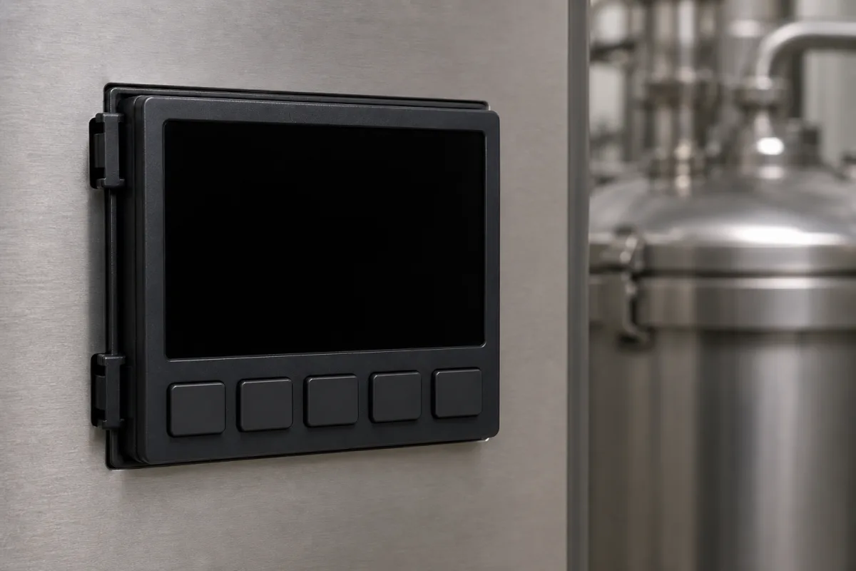
The keypad overlay and display window on a controller front
The illustrated unit is a dark front panel on a stainless cabinet beside process tanks: a large display window above a row of five keys. On a membrane keypad the keys and the window are one printed film, the overlay of the switch, laminated over the switch circuit and bonded to the housing. Two membrane switch makers' design guides and a hard-coated polyester film datasheet set out what that film has to withstand.
Covers membrane keypad overlays with integral display windows on the front of temperature controllers, process controllers and similar equipment: overlay film choice, hard coats and window textures, chemical and flex resistance, operating temperature of switch and domes, and mounting adhesive. Rubber keymats over metal domes are on the Keypad assembly page (2871); push-and-turn knob interfaces on 5279; HVAC room display units on 4941; HMI front IP ratings and screen design on 3992; TFT panel defect acceptance on 4982.
CNFX editorial research · Sources checked October 13, 2026 · 3 sources
Overlay film: what survives a million presses and the cleaning cloth
Nelson-Miller's membrane switch design guide gives the life-cycle result that decides the film: in its testing polyester shows no signs of wear at 1,000,000 cycles, while polycarbonate begins to crack as early as 40,000 cycles.
Nelson-Miller states that polycarbonate once had a price advantage and is still used for certain applications, and on that life data recommends polyester. The Autoflex sheet adds that the hard coat resists cleaners even at the overlay edges.
On equipment that is wiped down with cleaning and sanitising agents, the overlay is the part in contact with them; the chemical list above is what to compare against the plant's cleaning agents (editorial reading).
< 5% haze after 100 cycles, CS10F wheel, 500 g (gloss)
Autoflex EB datasheet
Pencil hardness
3H
Autoflex EB datasheet
The Autoflex EB datasheet is a 2001 Autotype issue hosted on a Siemens server; check the current grade with the film supplier.
02
The display window: clear print, hard coat and texture
Nelson-Miller explains that the overlay starts clear and colours are printed on its back; any area left unprinted becomes a window.
Epec adds two layout limits: LEDs cannot come through the active area of a tactile key, though graphics can make them appear part of it, and a matte or textured finish diffuses LED indicators better.
For a large LCD behind the window, as on the illustrated unit, the display-to-overlay gap and the window finish are therefore one decision (editorial reading of the Nelson-Miller guidance).
Point
Source
Uncoated glossy polyester and polycarbonate are very susceptible to scratching; gloss materials should always be hard-coated
Nelson-Miller
UV-cured hard coats screen-printed in selected areas can be used to coat windows
Nelson-Miller
Window coatings are a trade-off between anti-glare and optical clarity; the closer the display to the overlay, the less the coating affects readability
Nelson-Miller
For LED displays more than 0.062 in (1.6 mm) behind the overlay, a gloss or anti-glare window is recommended
Nelson-Miller
A textured hard coat on glossy or anti-glare material gives the best display windows
Epec
Film finishes: gloss (93% gloss level) or anti-glare (55%), in 130, 180 and 250 µm
Autoflex EB datasheet
03
Bonding the overlay and the temperatures it takes
A membrane keypad is shipped with a pressure-sensitive adhesive on its back and is bonded to the panel; Nelson-Miller names the adhesives by surface.
A controller mounted on the outside of a heated tank or near a hot process can sit above the 55 °C limit for polyester domes while staying inside the switch's 75 °C rating, which points to stainless steel domes for such a position (editorial reading).
Epec describes the sealed construction of membrane switches as the reason they are used where frequent cleaning is an issue; the seal at the panel then depends on the adhesive and the overlay edge.
Item
Figure or practice
Source
Smooth metal and high-surface-energy plastics
3M 467MP
Nelson-Miller
Rougher surfaces
3M 468MP
Nelson-Miller
Powder-coated and other low-surface-energy surfaces
Specific low-surface-energy adhesives
Nelson-Miller
Surface preparation
Clean the surface before installing
Nelson-Miller
Switch operating temperature
−20 °C to +75 °C
Nelson-Miller
Polyester domes
Relax and lose tactile feel at elevated temperature; not recommended above 55 °C
Nelson-Miller
Film dimensional stability
0.3% maximum shrinkage at 120 °C
Autoflex EB datasheet
UV exposure
Limited long-term UV resistance; not recommended for prolonged outdoor use
Autoflex EB datasheet
04
What to give a keypad and overlay supplier
Paste it into your enquiry below or into an email to a maker, then replace every bracket.
Give the panel material and finish the overlay bonds to, key layout and legends, display type and its distance behind the overlay, required key life, cleaning and sanitising agents used on the equipment, ambient and surface temperatures at the panel, indoor or outdoor use, and tactile or non-tactile keys. Ask for the overlay film and hard coat, window finish, chemical resistance test results against your agents, dome type, rated switch life and temperature range, and adhesive type.
Suppliers listed for keypad and display interfaces
1 company lists this product among what they make. Company figures are quoted from each
company's own website; every card states where the relationship came from.
Keypado
card
Lists industrial metal, piezo and backlit keypads, including keypads with display screens. Location TBC.
Explore company information and manufacturing capabilities, then discuss the scope of your project with a relevant supplier.
Share this page
Compiled and source-reviewed by the CNFX editorial team.
Each manufacturer above links to the page on that company's own website where the product is listed, with the date we checked it. How we source and review
· Page last updated 13 October 2026
Buyer questions
Polyester or polycarbonate for a keypad overlay?
Nelson-Miller's design guide reports polyester with no wear at 1,000,000 cycles and polycarbonate cracking as early as 40,000 cycles, and recommends polyester. [1]
Which chemicals does a hard-coated polyester overlay resist?
Autotype's Autoflex EB datasheet lists alcohols, dilute acids and alkalis, esters, hydrocarbons, ketones and household cleaning agents, tested to DIN 42 115. [3]
How do you make a display window readable through a keypad overlay?
Leave the area unprinted and hard-coat it; Epec states a textured hard coat on glossy or anti-glare material gives the best display windows. [2][1]
Sources and what still needs a direct check
Sources checked 2026-10-13. Membrane switch design guides from Nelson-Miller and Epec, and Autotype's datasheet for a hard-coated polyester overlay film.