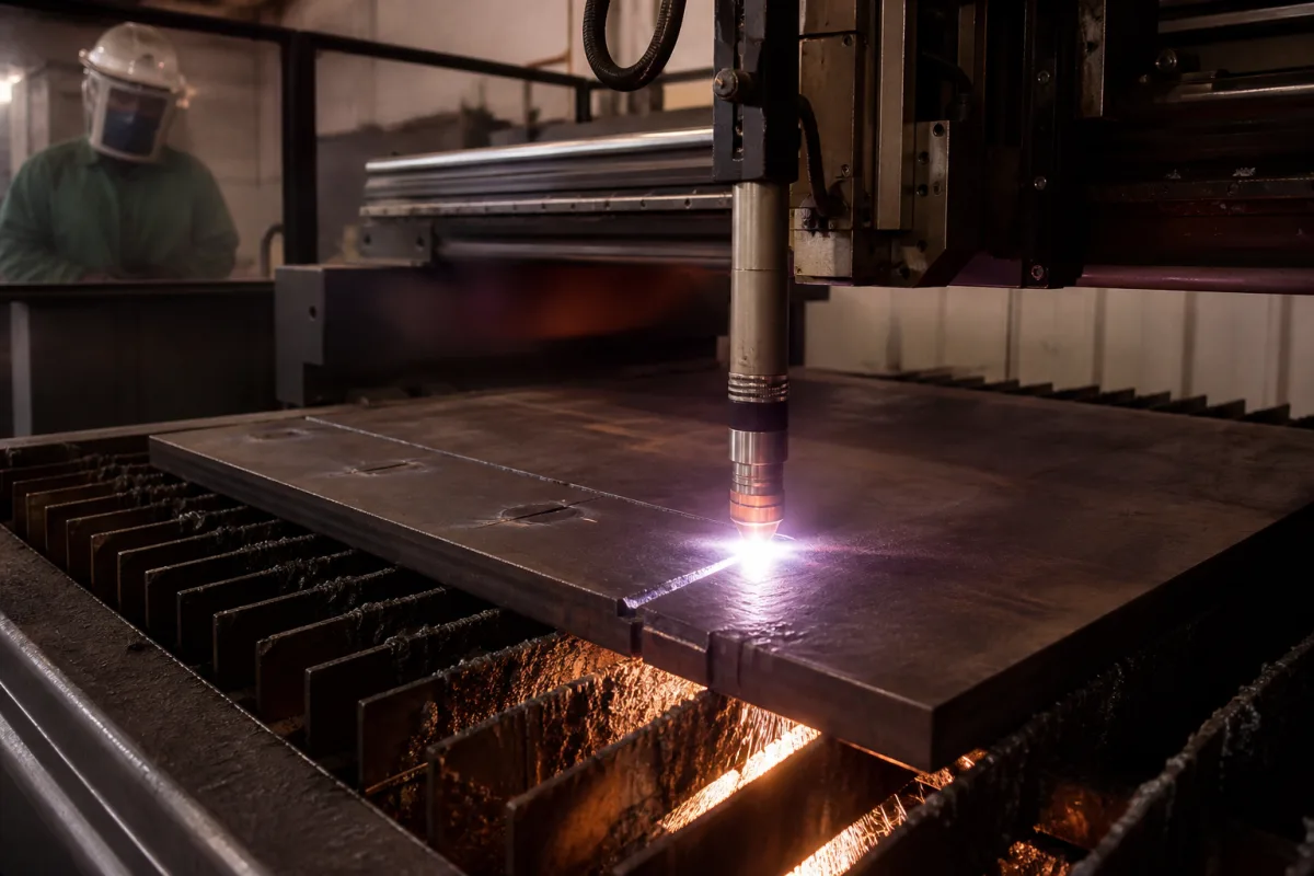
Cutting torch for CNC plasma machines: how the electrode and nozzle wear, when to change them, and how cooling and arc ramp-down extend their life
Machine plasma torches on CNC cutting tables · Hafnium pit depth at changeout, electrode and nozzle wear per pierce and per cut, liquid cooling above 100 A, current and gas ramp-down at the end of the cut
This page covers the torch itself on a mechanized plasma cutting machine: the straight-barrel torch on the gantry carriage and its stack of electrode, swirl ring, nozzle, retaining caps and shield. Ask three things first: how the electrode and nozzle are judged worn and replaced, whether the torch is liquid- or gas-cooled for the current you will cut at, and whether the system ramps gas and current down at the end of each cut.
Machine plasma cutting torches for CNC tables, their consumable stacks and their wear, cooling and changeout. Complete gantry machines with their sources, drives and height control are covered on the CNC gantry plasma cutting machine page, which also lists part numbers for one air-plasma machine torch, and plasma power sources on the Plasma power supply page. Hand-held plasma torches, oxy-fuel cutting torches, welding torches (covered on the Welding torch page) and laser cutting heads are outside this page.
CNFX editorial research · Sources checked October 12, 2026 · 5 sources
Hafnium wears at every start and stop: pierces, cut length and current decide electrode life
In The Fabricator, Hypertherm's torch and consumables product marketing manager names three factors that set consumable life in a properly working system: the number of pierces, because arc initiation and termination erode the hafnium; cut duration, because heat during long cuts erodes it; and material thickness, because thicker plate needs more current, which erodes it faster. [1] A second Fabricator article adds that a new electrode wears rapidly over about the first and last 10 percent of its life and slowly and predictably in between, and that longer cuts mean fewer starts and longer electrode life. [3]
Hypertherm's US patent 5,070,227 states that hafnium is the best emitter choice for reactive-gas plasma, yet electrodes cutting with oxygen or air need replacement after 0.5 to 2 hours of use depending strongly on the number of on-off cycles; for its MAX 100 torch it reports a pit about 0.025 in deep after 120 cut cycles and recommends replacement at 0.060 in. [4]
The same patent reports that reducing gas flow and ramping the arc current down together at shut-off cut the MAX 100 pit to about 0.005 in after 120 cycles, which it describes as five times the electrode life, with a ramp interval of roughly 250–300 ms found best for the MAX 200. [4] Editorial calculation: at 0.025 in per 120 cycles, a straight-line estimate reaches 0.060 in after about 290 cycles; at 0.005 in per 120 cycles, after about 1,440. Wear is not linear across the electrode's life, so treat these as rough. [4][3]
Give the supplier the material grades and thicknesses, the cutting current and gases, the pierces per plate and the average cut length, so consumable life can be estimated for your parts rather than quoted per hour.
02
Measuring the hafnium pit, reading the nozzle orifice and the 1-to-1 or 2-to-1 changeout ratio
The Fabricator's rule of thumb is to change standard all-copper electrodes at a hafnium pit depth of 0.040 to 0.050 in, and silver/hafnium interface electrodes at 0.080 to 0.100 in; as a guide the nozzle-to-electrode changeout ratio is 1-to-1 for all-copper electrodes and can be 2-to-1 for silver/hafnium ones, and a well-kept swirl ring can last 10 to 15 nozzle/electrode changes. [1] Pit depth is read with a dial indicator zeroed on a new electrode of the same part number; in its example, a 0.023 in pit against a 0.040 in maximum leaves about 43 percent of life. [2]
The nozzle has no single measurable attribute, so its inlet and outlet orifice are inspected for wear: sharp edges on a new nozzle round off with use and eventually spoil cut quality. [2] Pits between 0.045 and 0.050 in can cause dross and angularity and, beyond that, a catastrophic failure that damages the nozzle, shield and possibly the coolant tube. [3]
Both Fabricator articles warn against changing consumables on a fixed count of pierces or at every shift, because wear is application-specific and good parts get scrapped. [1][2]
03
Liquid-cooled electrodes above 100 A and what a discoloured electrode says about cooling
The Fabricator states that electrodes carrying more than 100 A of cutting current are, with few exceptions, liquid-cooled, with gas-cooled electrodes in smaller mechanized and hand-held systems; the hafnium emitter can exceed 3,000 °F, and coolant forced through a tight fit around the electrode's hollow mill raises coolant velocity. A nicked coolant tube gives uneven flow and shortens electrode life. [3] Hypertherm's patent describes water cooling as expensive, cumbersome and not desirable for low-current units rated below 100 A, and air cooling as less efficient and limiting the maximum operating current. [4]
The electrode's copper body should stay clean and shiny to the end of its life; grey heat discoloration can point to a cooling problem, and an off-centre pit to a gas flow problem such as a wrong or damaged swirl ring. [2][3]
04
End the cut on the plate: ramp-down errors and gas supply at the start
Oxygen-capable systems extend consumable life by ramping gas pressure and current at the start and end of each cut, and arc termination matters more than any other phase; the ramp works only when the cut ends on the plate. A ramp-down error where the arc runs off the plate ejects hafnium and costs between 10 and 15 arc starts, and for holes the CNC can be programmed without a lead-out. Low plasma gas flow at the start of a job can notch the nozzle. [1]
1 company lists this product among what they make. Company figures are quoted from each
company's own website; every card states where the relationship came from.
Explore company information and manufacturing capabilities, then discuss the scope of your project with a relevant supplier.
Share this page
Compiled and source-reviewed by the CNFX editorial team.
Each manufacturer above links to the page on that company's own website where the product is listed, with the date we checked it. How we source and review
· Page last updated 13 October 2026
Buyer questions
When should a plasma torch electrode be changed?
The Fabricator gives 0.040 to 0.050 in hafnium pit depth for standard all-copper electrodes and 0.080 to 0.100 in for silver/hafnium electrodes, measured with a dial indicator against a new electrode. [1][2]
What shortens consumable life in mechanized plasma cutting?
Pierces, long cuts and high current for thick plate erode the hafnium, and a cut that ends off the plate can cost between 10 and 15 arc starts. [1]
Does gas and current ramp-down really help?
Hypertherm's patent reports pit wear of about 0.005 in instead of 0.025 in after 120 cycles on its MAX 100 torch with ramp-down. [4]
Sources and what still needs a direct check
Sources checked 2026-10-12. Three Fabricator articles, one written by a Hypertherm consumables marketing manager, describe consumable wear and changeout; a Hypertherm patent reports measured electrode wear; Huarui lists its own torch.