Editorial Technical Reference

Air Distribution System

This page explains how Air Distribution System is classified within Machinery and Equipment Manufacturing. Technical values and manufacturer relationships are research references; confirm the current specification and supplier evidence for each order.

Technical Definition & Core Assembly

A subsystem within a diaphragm pump that controls and directs compressed air flow to actuate the diaphragm.
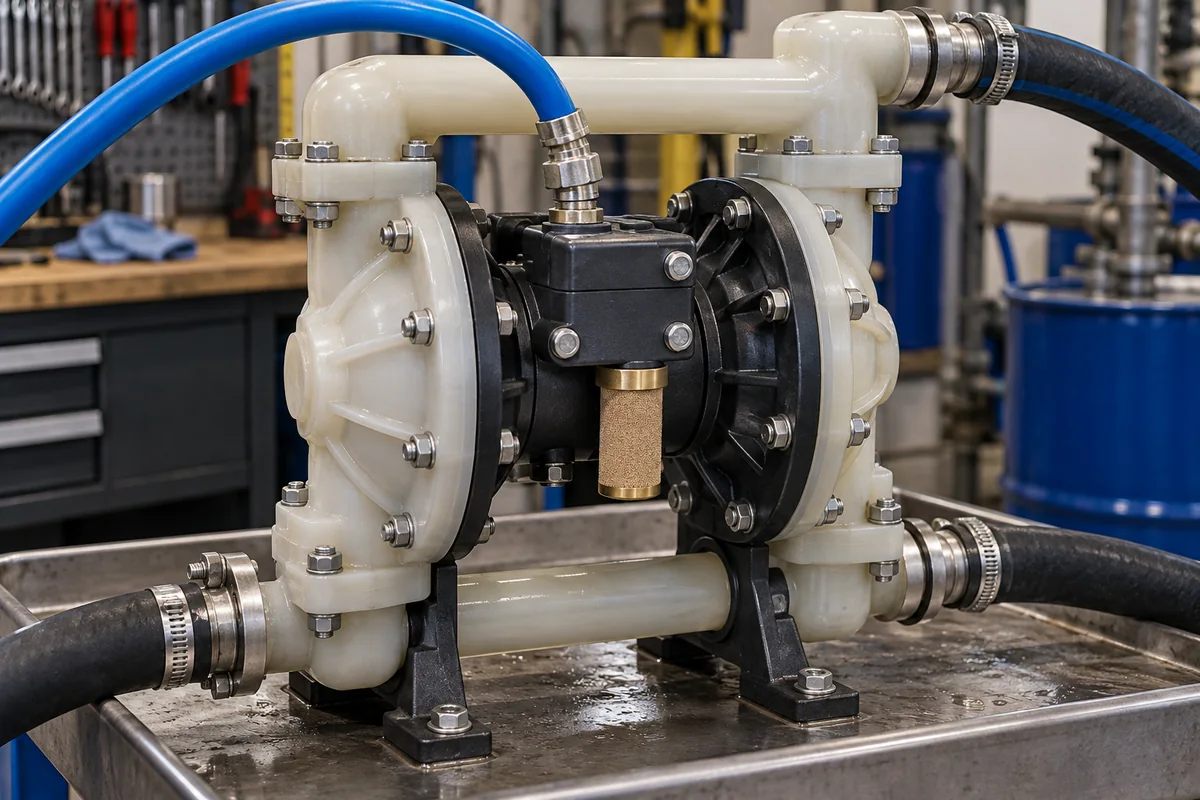
Representative product image. Confirm appearance and specifications with the manufacturer.

Product Specifications

Technical details and manufacturing context for Air Distribution System

Definition
The air distribution system is a critical component of an air-operated double diaphragm (AODD) pump. It functions as the control mechanism that alternately directs compressed air to each side of the diaphragm assembly, creating the reciprocating motion that drives fluid transfer. It typically consists of an air valve, distribution channels, and connections to the pump's air chambers. The system is designed to operate within specific parameters, including a maximum inlet air pressure of 6.9–8.6 bar (ISO 1217), air consumption at rated flow of 0.5–2.5 m³/min (ISO 1217), and a valve response time of 0.05–0.2 seconds. Internal leakage rates are typically 0.1–0.5 L/min (ISO 8573-1), and the operating temperature range is -10 to +80°C, extendable to -20 to +120°C with PTFE seals. Port connection sizes range from 1/4 to 1 inch NPT (ASME B1.20.1). For externally piloted valves, pilot air pressure is 2–6 bar. Cycle life is typically 10–50 million cycles, depending on materials and load. Materials of construction include aluminum 6061-T6, 316L stainless steel, PTFE, and PEEK, with surface finish of internal passages at Ra 0.8–1.6 µm (ISO 1302). The system requires inlet air pressure within 2–8.6 bar and ambient temperature within -10 to +80°C. Air quality should meet ISO 8573-1 Class 3 for particles and Class 4 for moisture. Lubrication can be non-lubricated or with compatible oil. These values are reference ranges; verify model-specific data with the manufacturer.
Working Principle
Compressed air enters the system and is directed by an internal air valve (often a spool or shuttle valve) to one side of the diaphragm. This pressurizes the air chamber, forcing the diaphragm to flex and displace fluid on the opposite side. Simultaneously, the valve exhausts air from the other chamber, allowing its diaphragm to return. The valve then shifts, reversing the air flow to the opposite chambers, creating a continuous pumping cycle.
Common Materials
Aluminum Alloy, Stainless Steel, Engineering Plastics (e.g., PTFE, PEEK)
Technical Parameters
ParameterTypical rangeNotes & selection driver
Maximum inlet air pressure6.9–8.6 bar6.9–8.6 — For standard diaphragm pumps; higher pressures may require reinforced housing. For standard diaphragm pumps; higher pressures may require reinforced housing.ISO 1217
Air consumption at rated flow0.5–2.5 m³/min0.5–2.5 — Depends on pump size and stroke frequency. Depends on pump size and stroke frequency.ISO 1217
Valve response time0.05–0.2 s0.05–0.2 — Time for spool to shift from one position to the other. Time for spool to shift from one position to the other.
Leakage rate (internal)0.1–0.5 L/min0.1–0.5 — At rated pressure; higher leakage reduces efficiency. At rated pressure; higher leakage reduces efficiency.ISO 8573-1
Operating temperature range-10–+80 °C-10 to +80 — For standard elastomers; PTFE seals extend range to -20 to +120°C. -10 to +80 — For standard elastomers; PTFE seals extend range to -20 to +120°C. Outside this range: Below -10°C: elastomers become brittle and crack; above 80°C: seals degrade and leak.
Port connection size1/4–1 inch NPT1/4 to 1 — Inlet and outlet ports; size depends on pump flow rating. Inlet and outlet ports; size depends on pump flow rating.ASME B1.20.1
Pilot air pressure (if applicable)2–6 bar2–6 — For externally piloted valves; not required for self-actuating designs. For externally piloted valves; not required for self-actuating designs.
Cycle life10–50 million cycles10–50 — Depends on materials and load; PTFE seals last longer than NBR. Depends on materials and load; PTFE seals last longer than NBR.
Materials of constructionAluminum 6061-T6, 316L stainless steel, PTFE, PEEKAluminum 6061-T6, 316L stainless steel, PTFE, PEEK — Aluminum for body, stainless for spool, PTFE for seals, PEEK for bushings. Aluminum for body, stainless for spool, PTFE for seals, PEEK for bushings.ASTM B221, ASTM A276
Surface finish (internal passages)Ra 0.8–1.6 µmRa 0.8–1.6 — Smoother finish reduces friction and wear. Smoother finish reduces friction and wear.ISO 1302
Inlet air pressure2–8.6 bar2–8.6 bar — Outside this window: Below 2 bar: valve may not shift reliably; above 8.6 bar: risk of seal extrusion and housing rupture. Outside this window: Below 2 bar: valve may not shift reliably; above 8.6 bar: risk of seal extrusion and housing rupture.
Air quality (particulate and moisture)ISO 8573-1 Class 3 (particles) and Class 4 (moisture)ISO 8573-1 Class 3 (particles) and Class 4 (moisture) — Outside this window: Higher contamination accelerates wear of spool and seals, leading to sticking and leakage. Outside this window: Higher contamination accelerates wear of spool and seals, leading to sticking and leakage.
LubricationNon-lubricated or lubricated with compatible oilNon-lubricated or lubricated with compatible oil — Outside this window: Incompatible oil can swell elastomers; lack of lubrication in lubricated designs causes premature wear. Outside this window: Incompatible oil can swell elastomers; lack of lubrication in lubricated designs causes premature wear.

Ranges are indicative industry figures for RFQ preparation, not a supplier commitment. Confirm every value and standard with the legal manufacturer before ordering.

Components / BOM
  • Air Valve (Spool/Shuttle)
    Directs the flow of compressed air alternately to each pump chamber.
    Material: Stainless Steel, Aluminum, Engineering Plastic
  • Valve Housing/Body
    Encloses the valve mechanism and provides connection ports for air lines.
    Material: Aluminum Alloy, Stainless Steel, Cast Iron
  • Air Inlet/Outlet Ports Part
    Connection points for the main air supply and exhaust lines.
    Material: Metal (with threaded fittings)
  • Pilot Valve (if applicable) Optional
    A smaller valve that uses air pressure to signal the main valve to shift.
    Material: Engineering Plastic, Metal

Applied To / Applications

This component is essential for the following industrial systems and equipment:

Industrial Ecosystem & Supply Chain Structure

Complementary Systems
Downstream Applications
Specialized Tooling

Application Fit & Sizing Matrix

What Decides the Award
  • What is the maximum inlet air pressure and flow rate required for the pump application?
  • What are the operating temperature extremes and chemical exposure?
  • What is the acceptable internal leakage rate and how is it tested?
  • What is the required cycle life and what maintenance interval is acceptable?
  • What are the port connection sizes and thread standards needed?
  • Does the system require external piloting or is self-actuating sufficient?
  • What is the target cost and lead time?
Failure Modes & Inspection
  • Valve sticking
    Check: Cycle test at rated pressure and frequency; measure response time and listen for erratic operation.
  • Internal leakage
    Check: Pressure decay test: pressurize one port and measure pressure drop over time; compare to spec.
  • External leakage
    Check: Visual inspection and bubble test with soap solution at rated pressure.
  • Premature wear
    Check: Disassemble and measure spool and bore dimensions; check for scoring and seal condition.

Reliability & Engineering Risk Analysis

Failure Mode & Root Cause
Corrosion-induced leakage
Cause: Moisture accumulation in compressed air leading to internal rusting of pipes and fittings, accelerated by acidic condensate and lack of proper air drying systems.
Filter blockage and pressure drop
Cause: Accumulation of particulates, oil aerosols, and moisture in filters due to inadequate filtration maintenance, contaminated intake air, or failing compressor oil separators.
Maintenance Indicators
  • Audible hissing or whistling from fittings, valves, or connections indicating air leaks
  • Visible moisture or oil droplets at drain points, filters, or downstream equipment
Engineering Tips
  • Implement routine moisture control: Install and maintain refrigerated or desiccant air dryers, ensure automatic drains function properly, and monitor dew point to prevent corrosion and contamination.
  • Establish proactive filter maintenance: Use differential pressure gauges across filters to schedule replacements before bypass occurs, and select appropriate filter grades (particulate, coalescing, adsorption) based on air quality requirements.

Indicative industry ranges for design and RFQ preparation. Confirm the exact figures and applicable standard with the manufacturer before specifying.

Compliance & Manufacturing Standards

Applicable Standards
ISO 8573-1:2010 (Compressed air quality classes) ANSI/ASHRAE 62.1-2022 (Ventilation for acceptable indoor air quality) DIN 1946-4:2018 (Ventilation and air conditioning in hospitals)

Quoted from the published standard.

Manufacturing Precision
  • Ductwork alignment: +/- 3mm per meter length
  • Airflow rate: +/- 10% of design specification
Quality Inspection
  • Pressure decay leak test (per ISO 8573-2)
  • Airflow measurement and balancing verification

Manufacturers of Air Distribution System

Manufacturer profiles associated with Air Distribution System.

Sourcing Air Distribution System from China?
Tell us your specification and target quantity — we will match it against manufacturer records and come back with the factories that fit.
Request manufacturers We manufacture this

Manufacturer listings support early research and capability understanding. They are not certification, ranking, or transaction guarantees.

Technical documentation
Request current drawings, revision history, and a signed specification sheet.
Manufacturing capability
Verify equipment lists, process limits, capacity, and representative production evidence.
Inspection readiness
Confirm test methods, calibrated equipment, sampling plans, and traceable reports.
Supplier transparency
Check the legal entity, factory address, ownership, certifications, and direct contacts.

CNFX does not score or rank suppliers. Buyers must verify all claims and documents with the legal manufacturer before ordering.

Supply Chain Compatible Machinery & Devices

Hydraulic Press

Industrial machine using hydraulic pressure to compress, form, or assemble materials

Explore Specs →
Heavy-Duty CNC Plasma Cutting Machine

The Heavy-Duty CNC Plasma Cutting Machine is a standalone industrial device designed for cutting conductive metals such as steel, stainless steel, aluminum, and copper alloys.

Explore Specs →
Automated Powder Coating System

Integrated industrial system for applying dry powder coatings to metal substrates.

Explore Specs →
Centrifugal Pump Impeller

The centrifugal pump impeller is a critical rotating component that converts mechanical energy from the motor into kinetic energy in fluid systems.

Explore Specs →

Frequently Asked Questions

What is the function of an air distribution system in a diaphragm pump?

It controls and directs compressed air alternately to each side of the diaphragm, creating reciprocating motion that drives fluid transfer.

What are typical operating pressure ranges for this component?

Maximum inlet air pressure is typically 6.9–8.6 bar, and inlet air pressure should be within 2–8.6 bar for reliable operation.

Which materials are commonly used in its construction?

Common materials include aluminum 6061-T6, 316L stainless steel, PTFE, and PEEK, as listed in the directory.

What standards apply to this component?

Relevant standards include ISO 1217 for performance testing, ISO 8573-1 for air quality, ASME B1.20.1 for ports, and ASTM B221/A276 for materials.

Data Basis

Editorial classification, named public sources where available, and source-reviewed manufacturer records.

Preliminary Technical Classification
This page supports structured research, RFQ preparation, and supplier evaluation. It does not replace buyer-led supplier qualification, standards review, or technical approval.
Buyer enquiry

Request manufacturing insight for Air Distribution System

Ask for use case, specification boundaries, supplier type, and RFQ preparation information for this product.

Where it goes
Straight to the CNFX editorial desk, and to the manufacturer if this product is linked to a claimed profile. Nothing is broadcast to a supplier list.
Your details stay here
We do not sell or rent enquiry data, and we do not add you to a mailing list. Used only to answer this request.
No commission, no middleman
CNFX is a directory. We take no cut of any order and never negotiate on a supplier's behalf.
What we don't claim
A listing is not an endorsement. Qualify every supplier and verify every figure yourself before ordering.

Your business information is used only to process this request.

Thank you! Your message has been sent. We'll respond within 1–3 business days.
Sorry, we couldn't send your message. Please try again, or email us at contact@cnfx.com.

Need to Manufacture Air Distribution System?

Compare manufacturer profiles with relevant product and process capability.

Previous Product
Air Distribution Plenum
Next Product
Air Handling Unit
Get QuotesChat