Editorial Technical Reference

Cooling Water Header/Piping

This page explains how Cooling Water Header/Piping is classified within Machinery and Equipment Manufacturing. Technical values and manufacturer relationships are research references; confirm the current specification and supplier evidence for each order.

Technical Definition & Core Assembly

A piping network that distributes cooling water from the main supply to various heat exchange points within the secondary cooling system.
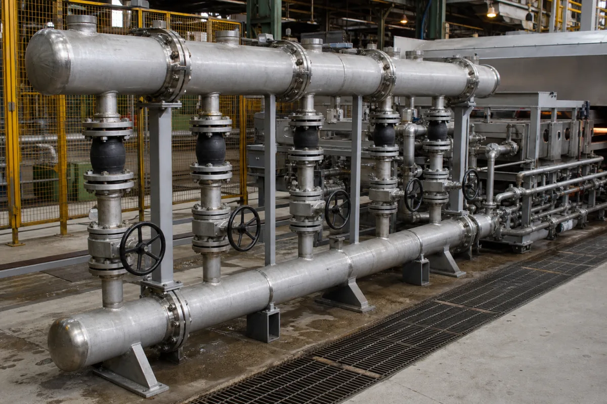
Representative product image. Confirm appearance and specifications with the manufacturer.

Product Specifications

Technical details and manufacturing context for Cooling Water Header/Piping

Definition
The Cooling Water Header/Piping is a critical component of the Secondary Cooling System that serves as the main distribution conduit for chilled or cooled water. It collects water from the primary cooling source (such as chillers or cooling towers) and routes it through a network of pipes to multiple heat exchange units, equipment, or processes requiring temperature control. This system ensures uniform cooling distribution while maintaining proper flow rates and pressure throughout the facility. The header is typically a larger-diameter pipe that acts as a manifold, with branch lines extending to individual cooling points. The piping network is designed to handle specified flow rates and pressures, with materials selected based on the cooling water chemistry and operating environment. Common materials include carbon steel, stainless steel, PVC, and copper, each offering different corrosion resistance and mechanical properties. The system operates within defined parameters such as nominal diameter (DN50–DN300), wall thickness (3.0–12.0 mm), operating pressure (1.0–1.6 MPa), and design temperature (-10–80°C). Flow velocity is typically maintained between 1.5 and 3.0 m/s to balance heat transfer efficiency and erosion concerns. Pressure drop across the system is limited to 0.05–0.15 MPa to ensure adequate cooling performance. Material grades like 304 or 316L are specified for corrosion resistance, with 316L offering better performance in seawater applications. Corrosion allowance of 1.5–3.0 mm is considered for aggressive water conditions. Flange ratings (PN16–PN25) must match the operating pressure. Insulation thickness of 25–50 mm prevents condensation and heat gain. Weight per meter ranges from 10–50 kg/m, affecting support spacing and installation cost. Leakage rate is limited to ≤0.1% to ensure sealing integrity. These parameters are reference ranges; actual values must be confirmed with the manufacturer for specific applications. The system is designed to operate within these limits to ensure reliable cooling and long service life.
Working Principle
Cooling water is pumped from the primary cooling equipment into the header, which acts as a main distribution manifold. From there, it flows through branching pipes to various endpoints where heat exchange occurs. The water absorbs thermal energy from processes or equipment, then returns through a separate return header to be re-cooled, creating a continuous closed-loop or open-loop cooling cycle. The header ensures even distribution and maintains required flow and pressure.
Common Materials
Carbon Steel, Stainless Steel, PVC, Copper
Technical Parameters
ParameterTypical rangeNotes & selection driver
Nominal DiameterDN50–DN300 mmDetermines flow capacity and compatibility with flanges.ISO 6708
Wall Thickness3.0–12.0 mmAffects pressure rating and corrosion allowance.ISO 4200
Operating Pressure1.0–1.6 MPa
Design Temperature-10–80 °CExceeding 80°C may degrade gasket materials.ISO 4126
Flow Velocity1.5–3.0 m/sHigher velocity increases erosion and pressure drop.ISO 10780
Pressure Drop0.05–0.15 MPaExcessive drop reduces cooling efficiency.ISO 5167
Material Grade304/316L316L offers better corrosion resistance for seawater.ASTM A312
Corrosion Allowance1.5–3.0 mmHigher allowance extends service life in aggressive water.ISO 9227
Flange RatingPN16–PN25 barMust match pipe operating pressure.ISO 7005
Insulation Thickness25–50 mmPrevents condensation and heat gain.ISO 12241
Weight per Meter10–50 kg/mAffects support spacing and installation cost.ISO 4200
Leakage Rate≤0.1 %Higher leakage indicates poor sealing.

Ranges are indicative industry figures for RFQ preparation, not a supplier commitment. Confirm every value and standard with the legal manufacturer before ordering.

Components / BOM
  • Header Manifold
    Main distribution point where cooling water is divided into multiple branch lines
    Material: Carbon Steel or Stainless Steel
  • Branch Pipes Part
    Individual pipes that carry cooling water from the header to specific equipment or zones
    Material: Carbon Steel, Copper, or PVC
  • Isolation Valves
    Allow sections of the piping to be shut off for maintenance without affecting the entire system
    Material: Brass or Stainless Steel
  • Support Brackets Part
    Secure the piping system to building structures and prevent sagging or vibration
    Material: Galvanized Steel
  • Return Header
    Collects the warmed water from all branches and sends it back to be re-cooled.

Industry Taxonomies & Aliases

Commonly used trade names and technical identifiers for Cooling Water Header/Piping.

Applied To / Applications

This component is essential for the following industrial systems and equipment:

Industrial Ecosystem & Supply Chain Structure

Complementary Systems
Downstream Applications
Specialized Tooling

Application Fit & Sizing Matrix

Operational Limits
pressure: Up to 150 psi (10.3 bar)
flow rate: Up to 5000 GPM (18,927 L/min)
temperature: 5°C to 50°C (41°F to 122°F)
slurry concentration: Not applicable - designed for clean water service only
Media Compatibility
✓ Industrial cooling water (treated) ✓ Closed-loop glycol solutions ✓ Process water (pH 6-8)
Unsuitable: Corrosive chemicals or abrasive slurries
Sizing Data Required
  • Total system flow rate (GPM/LPM)
  • Required pressure drop across system (psi/bar)
  • Number and type of heat exchange points to be served

Reliability & Engineering Risk Analysis

Failure Mode & Root Cause
Corrosion-induced wall thinning
Cause: Chemical attack from dissolved oxygen, chlorides, or acidic contaminants in cooling water, accelerated by stagnant flow or microbiologically influenced corrosion (MIC).
Erosion-corrosion at bends and fittings
Cause: High-velocity water flow combined with suspended solids (e.g., sand, scale particles) leading to accelerated material loss, particularly at elbows, tees, and reducers.
Maintenance Indicators
  • Visible external corrosion, weeping, or pinhole leaks at pipe joints or supports
  • Audible water hammer or vibration noises indicating flow turbulence, air entrapment, or loose internal components
Engineering Tips
  • Implement routine water chemistry monitoring and treatment to control pH, hardness, and microbiological growth, reducing corrosive and fouling tendencies.
  • Install sacrificial anodes or cathodic protection at critical sections, and use non-destructive testing (e.g., ultrasonic thickness gauging) annually to track wall thickness trends.

Indicative industry ranges for design and RFQ preparation. Confirm the exact figures and applicable standard with the manufacturer before specifying.

Compliance & Manufacturing Standards

Applicable Standards
ISO 14692-1:2017 (Petroleum and natural gas industries - Glass-reinforced plastics (GRP) piping) ANSI/ASME B31.3:2022 (Process Piping) DIN 2448:2016-06 (Steel tubes - Dimensions)

Quoted from the published standard.

Manufacturing Precision
  • Wall Thickness: +/-10% of nominal thickness
  • Outer Diameter: +/-1% of nominal diameter
Quality Inspection
  • Hydrostatic Pressure Test (to 1.5x design pressure)
  • Ultrasonic Thickness Testing (for wall thickness verification)

Manufacturers of Cooling Water Header/Piping

Manufacturer profiles associated with Cooling Water Header/Piping.

Sourcing Cooling Water Header/Piping from China?
Tell us your specification and target quantity — we will match it against manufacturer records and come back with the factories that fit.
Request manufacturers We manufacture this

Manufacturer listings support early research and capability understanding. They are not certification, ranking, or transaction guarantees.

Technical documentation
Request current drawings, revision history, and a signed specification sheet.
Manufacturing capability
Verify equipment lists, process limits, capacity, and representative production evidence.
Inspection readiness
Confirm test methods, calibrated equipment, sampling plans, and traceable reports.
Supplier transparency
Check the legal entity, factory address, ownership, certifications, and direct contacts.

CNFX does not score or rank suppliers. Buyers must verify all claims and documents with the legal manufacturer before ordering.

Supply Chain Compatible Machinery & Devices

Hydraulic Press

Industrial machine using hydraulic pressure to compress, form, or assemble materials

Explore Specs →
Heavy-Duty CNC Plasma Cutting Machine

The Heavy-Duty CNC Plasma Cutting Machine is a standalone industrial device designed for cutting conductive metals such as steel, stainless steel, aluminum, and copper alloys.

Explore Specs →
Automated Powder Coating System

Integrated industrial system for applying dry powder coatings to metal substrates.

Explore Specs →
Centrifugal Pump Impeller

The centrifugal pump impeller is a critical rotating component that converts mechanical energy from the motor into kinetic energy in fluid systems.

Explore Specs →

Frequently Asked Questions

What is the purpose of a cooling water header?

The header collects cooling water from the primary source and distributes it to multiple heat exchange points, ensuring uniform flow and pressure.

What materials are commonly used?

Common materials include carbon steel, stainless steel, PVC, and copper. Selection depends on water chemistry and operating conditions.

What are typical operating pressure ranges?

Operating pressure is typically 1.0–1.6 MPa, but must be confirmed for the specific application.

How is corrosion handled?

Corrosion allowance of 1.5–3.0 mm is specified, and material grades like 316L are used for better resistance in aggressive environments.

Data Basis

Editorial classification, named public sources where available, and source-reviewed manufacturer records.

Preliminary Technical Classification
This page supports structured research, RFQ preparation, and supplier evaluation. It does not replace buyer-led supplier qualification, standards review, or technical approval.
Buyer enquiry

Request manufacturing insight for Cooling Water Header/Piping

Ask for use case, specification boundaries, supplier type, and RFQ preparation information for this product.

Where it goes
Straight to the CNFX editorial desk, and to the manufacturer if this product is linked to a claimed profile. Nothing is broadcast to a supplier list.
Your details stay here
We do not sell or rent enquiry data, and we do not add you to a mailing list. Used only to answer this request.
No commission, no middleman
CNFX is a directory. We take no cut of any order and never negotiate on a supplier's behalf.
What we don't claim
A listing is not an endorsement. Qualify every supplier and verify every figure yourself before ordering.

Your business information is used only to process this request.

Thank you! Your message has been sent. We'll respond within 1–3 business days.
Sorry, we couldn't send your message. Please try again, or email us at contact@cnfx.com.

Need to Manufacture Cooling Water Header/Piping?

Compare manufacturer profiles with relevant product and process capability.

Previous Product
Z-axis Ram/Spindle
Last Product
Get QuotesChat