CMMs · Reading ISO 10360-2 MPE_E specifications, the temperature band behind them, the room the machine needs, air and power
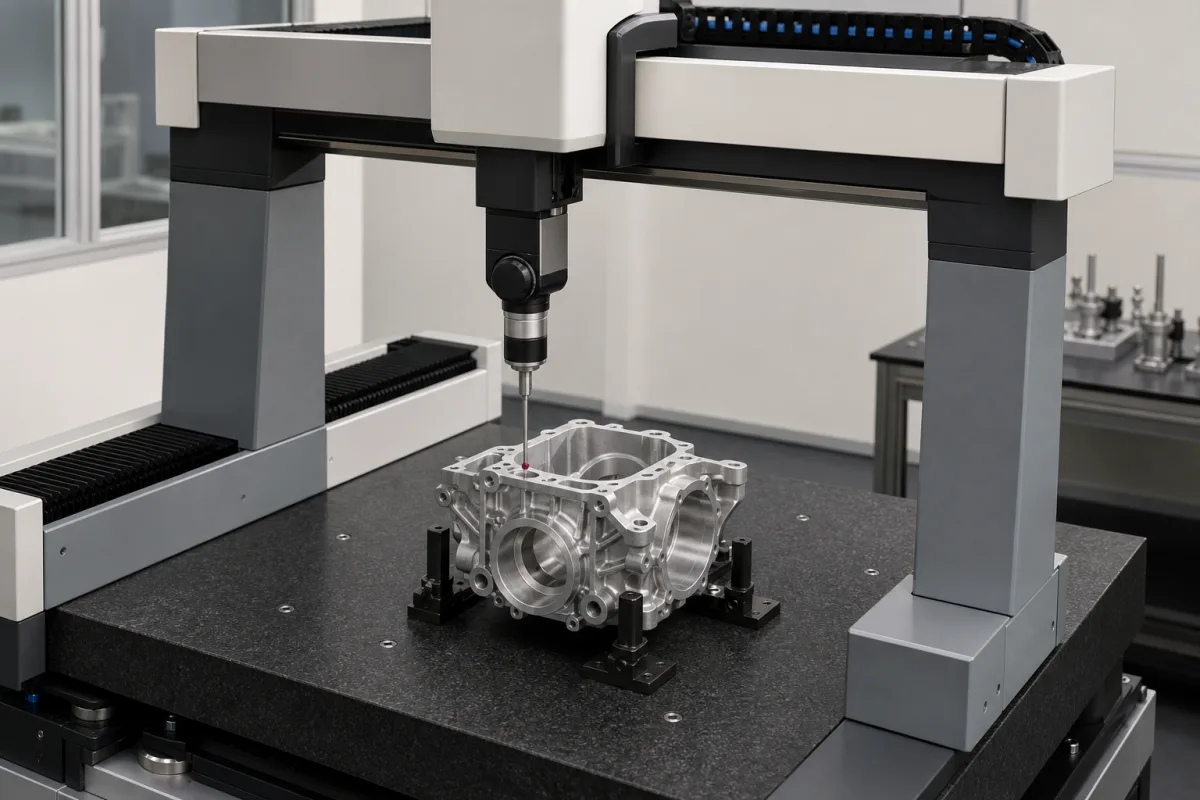
A coordinate measuring machine measures the geometry of parts by probing points on them in three axes, here on a granite table with air-bearing axes, as in the bridge machine pictured probing a cast housing. Ask three things first: what the length-measurement error (E0, MPE under ISO 10360-2) is at the lengths you measure, which temperature band and gradients that figure assumes, and what air, power and room conditions the machine needs to hold it.
Bridge, gantry and similar Cartesian coordinate measuring machines with tactile and optical probing. Portable measuring arms, laser trackers, vision measuring machines and CMM inspection services are outside this page.
CNFX editorial research · Sources checked October 12, 2026 · 4 sources
Hexagon's DELTA OPERA data sheet states specifications to ISO 10360-2:2009, ISO 10360-5:2010 and ISO 10360-4:2000. It explains the length-measurement error E0,MPE as five calibrated test lengths measured three times with one probing at each end in seven directions, all results within E0; E150 is the same with styli offset 150 mm from the Z axis; R0,MPL limits the repeatability range of those measurements; and PFTU,MPE is the single-stylus form error from 25 probings on a precision sphere. [1]
The errors are written as a constant plus a length-dependent term, with L in mm. Mitutoyo's CRYSTA-KM 565 manual machine (500 × 600 × 500 mm) specifies E0,MPE = (3.2 + 5L/1000) µm at 18 to 22 °C with an MH20i-TP20 probe and has 0.1 µm resolution scales. [2]
The standard behind these figures, ISO 10360-2:2009 (adopted in Sweden as SS-EN ISO 10360-2:2009, edition 3, approved 9 December 2009, 44 pages), specifies acceptance tests that verify a CMM's length-measuring performance as stated by the manufacturer, and reverification tests that let the user recheck it periodically. It applies only to Cartesian CMMs using contacting probing systems of any type in discrete-point probing mode; non-Cartesian machines and optical probing are not explicitly covered, though the parties may agree to apply it. It also sets the rules for proving conformance with the stated requirements. [3]
Editorial note: an MPE quoted for scanning or optical probing is outside the explicit scope of this part, so ask which other part of ISO 10360 (the Hexagon sheet also cites parts 4 and 5) the figure follows, and specify the acceptance test and reverification interval in the order. [3][1]
Editorial calculation: for that machine the maximum permissible length error is 3.2 + 5 × 300/1000 = 4.7 µm over a 300 mm feature and 5.7 µm over 500 mm. Compare this with your tolerances on the same lengths, and note that the figure applies to the stated probe and temperature conditions.
Give the supplier the largest part size and weight, the features and tolerances to be measured, the lengths involved, probing needs (touch-trigger, scanning, optical), required MPE values and standard, the room's temperature range and gradients, vibration, air and power available, throughput and software or reporting requirements.
02
Fix the temperature band and room conditions
Hexagon gives each DELTA OPERA model a different MPE for each temperature band. For the 20.yy.15 size with an HP-S-X5 probe, E0 is 3.2 + 3.0 L/1000 µm at 19–21 °C, 3.2 + 3.5 L/1000 µm at 18–22 °C and 3.6 + 5.2 L/1000 µm at 16–26 °C. The tests assume air temperature variation of no more than 0.5 °C/h and 1 °C/24 h in the 19–21 °C band, 1 °C/h and 2 °C/24 h at 18–22 °C, and 1 °C/h and 5 °C/24 h at 16–26 °C, with a vertical gradient of 1 °C/m. [1]
Editorial calculation: over a 1,000 mm length those figures give 6.2 µm, 6.7 µm and 8.8 µm respectively, so a looser room costs about 40% more permissible error at that length on this model. [1]
Mitutoyo's CRYSTA-KM 565 specifies a nominal 20 °C, an allowable range of 18–22 °C with gradients within 0.5 °C per hour and 2 °C per day, an operating range of 15–35 °C, 40–80% non-condensing humidity, and vibration limits of 30 mm/s² at 1–10 Hz, 15 mm/s² at 10–20 Hz and 50 mm/s² at 20–100 Hz. [2]
03
Plan air, power and installation
Both reviewed machines run on air bearings. Mitutoyo's CRYSTA-KM 565 needs a minimum air supply of 5 bar at 90 NL/min, and 230 V 50 Hz or 110 V 60 Hz at up to 10 A and 1,200 W. Hexagon's DELTA OPERA gantry needs air at 0.6 MPa minimum to ISO 8573-1 class 4, up to 400 Nl/min, and 1.6 kVA, with structural multi-sensor temperature compensation and an operating range of 10 to 45 °C. [2][1]
Editorial note: the operating range is where the machine will run, not where it meets its accuracy; specify the room to the band behind the MPE you are buying, and include the compressed-air dryer and filtration needed to reach the stated air class.
04
Bridge and cantilever CMMs with fixtures and calibration spheres
Listings include bridge and cantilever CMMs with fixtures and calibration accessories. Ask each supplier for the MPE values to ISO 10360 with the probe, temperature band and gradients they assume, the acceptance test it will run on site, and the calibration certificate.
05
Plan the acceptance test, reverification and interim checks
The UK National Physical Laboratory's Good Practice Guide No. 42, CMM Verification (Issue 2), describes the ISO 10360-2 length test: five test lengths are each measured three times in seven positions and orientations, four of them the space diagonals and three chosen by the user, giving 105 measurements. The longest length should be at least 66% of the longest space diagonal of the operating envelope and the shortest less than 30 mm. Up to five of the thirty-five test lengths may have one value above E0,MPE; each is then measured three more times, and all repeats must be within E0,MPE. [4]
For reverification, the 2009 edition lets the user state E0,MPE, R0,MPL and E150,MPE. NPL notes that Annex A of ISO 10360-2:2009 strongly recommends interim checks between reverifications, at an interval the user sets, and immediately after events such as a forklift strike or a significant temperature change. [4]
Editorial calculation: taking the CRYSTA-KM 565's 500 × 600 × 500 mm range as the envelope, its space diagonal is √(500² + 600² + 500²) ≈ 927 mm, so the longest test length should be at least about 612 mm. [2][4]
06
Granite base, bridge or gantry on air bearings, scales, probe head, temperature compensation and software
The probe row decides which MPE applies: ISO 10360-2 explicitly covers contacting probes in discrete-point mode, so a scanning or optical probe needs a figure from another part of ISO 10360. [3]
Measuring range, E0 and R0, scale resolution, room limits, air and power for a CMM order
Examples mix Mitutoyo's manual CRYSTA-KM 565 and Hexagon's DELTA OPERA gantry; quote E0 together with the probe and temperature band it was stated for.
2 companies list this product among what they make. Company figures are quoted from each
company's own website; every card states where the relationship came from.
Explore company information and manufacturing capabilities, then discuss the scope of your project with a relevant supplier.
Share this page
Compiled and source-reviewed by the CNFX editorial team.
Each manufacturer above links to the page on that company's own website where the product is listed, with the date we checked it. How we source and review
· Page last updated 13 October 2026
Buyer questions
What does a CMM accuracy of 3.2 + 5L/1000 µm mean?
It is the maximum permissible length error under ISO 10360-2, with L in mm; Mitutoyo's CRYSTA-KM 565 quotes it at 18–22 °C, giving about 5.7 µm over 500 mm (editorial calculation). [2]
Does room temperature change CMM accuracy?
Yes; Hexagon gives one DELTA OPERA model 3.2 + 3.0 L/1000 µm at 19–21 °C and 3.6 + 5.2 L/1000 µm at 16–26 °C. [1]
What air supply does a CMM need?
The reviewed machines need 0.5 to 0.6 MPa; Hexagon also specifies ISO 8573-1 class 4 air and up to 400 Nl/min. [1][2]
Does ISO 10360-2 cover optical or scanning CMMs?
Not explicitly: it applies to Cartesian CMMs with contacting probes in discrete-point mode, though the parties may agree to apply it to optical or non-Cartesian machines. [3]
What does an ISO 10360-2 CMM length test consist of?
NPL's Good Practice Guide No. 42 describes 105: five test lengths, each measured three times, in seven positions and orientations. [4]
Sources and what still needs a direct check
Sources checked 2026-10-12. Hexagon and Mitutoyo are CMM makers; their data sheets give values for their own machines tested to ISO 10360. The SIS scope page of ISO 10360-2:2009 defines what that part covers, and NPL's Good Practice Guide No. 42 explains the length test and reverification.